Mikołaj Koziarkiewicz
illustration banner
Illustration: own work[1] + background based on work of Ezi on Unsplash.


Intro

I’m sure most professional programmers by now have at least a passing familiarity with LLM-based coding assistants, whether through simple chat interfaces, or by trying not to get their prod data deleted by agentic approaches.

They’re not just a gimmick — they provide help with coding, apparent help with coding, and unambiguously deleterious "help" with coding. Key takeaway 💡: LLMs on occasion reduce cognitive load in 🧠 programming and OK, OK: I’ll stop with the oversaturated facsimile of stereotypical LLM writing patterns.

Regardless of what one might think about the current "AI" situation, coding agents, or even code-focused LLM chat assistants do help with the drudgery of programming on occasion.

Here, however, we’ll use both local and cloud-based LLMs to generate various outputs not traditionally thought of as "code": some to increase productivity or provide more options at work, and some to perhaps expand one’s overall toolset.

Before we proceed, one thing must absolutely be noted: for the topics covered, specialized models absolutely do already exist. The point here is not to show what can be done with modern models, but how already-familiar tools can be used in more ways, without any specialized knowledge, or additional deployment requirements.

Warmup: Making infographics

We’ll start with something more universally usable. On occasion, when communicating more complex messages to your coworkers/team, the text grows so rich in content, it becomes easy to lose the general view over the particulars. Which is where a graphical aid would come in handy – such as an infographic. But not everyone has the skills, patience, and/or time to create them, even when taking account the availability of various web tools meant for that purpose.

While it might seem counter-intuitive, generating graphics through a text-to-text coding-focused model is quite easy: just the matter of picking the right format; in our case, Scalable Vector Graphics (SVG).

SVGs are pretty much the most common files for vector graphics – primarily used for diagrams and illustrations – on the Web. The crucial bit about SVGs, however, is that internally, they’re just a completely human-readable XML file.

Here, let’s create a simple infographic for working with an LLM with the following prompt:

Create an SVG file representing a stylized infographic conveying the following information:

  • One of the primary uses of modern LLMs is coding assistance,

  • coding assistance supports both:

    • what’s traditionally seen as "coding languages", such as JavaScript, Java, Python, C/C++ and so on,

    • but also anything that can be expressed in a code like format: graphics, music, even models of physical objects.

  • while specialized models are usually better with all of that, being aware of the additional utility of general coding models gives you an advantage without the additional learning curve.

Keep the style clear, but in a typical infographic scheme. Enrich the infographic with small icons illustrating the most pertinent points.

Here’s one result, from Claude Sonnet 4.5 (through Copilot):

infographics sole claude45

This was obtained from just a single prompt, no followups, and looks relatively good!

If you’re curious about the code itself, download the SVG file and open it in a code editor.
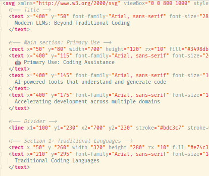
infographics code snippet claude45
Figure 1. A snippet of the resultant SVG file.

Local models don’t fare that well, comparatively, but still produce something approximating the desired result – here’s an example from GLM 4.5 Air after a couple of corrections:

infographic sole glm4.5 air reprompt

While this has some formatting issues, it at least provides a valid approximation of what we’d want. And the great thing about generating these graphics in format such as SVG, as opposed to your typical genAI model outputting raster images, is that you can easily edit the file and correct any problems.

To wit, this is the same file after ~3 minutes of editing in Inkscape:

infographic sole glm4.5 air reprompt edited
Figure 2. Some icons are still mispainted, but at least the layout is significantly improved.

In short, generating SVGs with LLMs conveys a similar advantage as with programming language code: it provides a decent "jump off" point, which then can be changed, refined, and generally made to one’s liking; or just help with writer’s block, especially when not having significant experience with graphic design.

Main course: Prompts to objects

Intro

Now, for our main course: we’ll take the same chat assistants we use for coding, and make them help us create actual physical objects, just from a short concept spec.

Well, OK, for that to happen, we also require a 3D printer. For those unfamiliar with 3D printing: an extremely simplified procedure to go from design to physical object is as follows:

  1. Design the object: typically in a CAD (Computer Aided Design) program, or via an equivalent coding framework (like OpenSCAD); alternatively, use a 3D editor like Blender.

  2. Export the design to a format expressing surface geometry of the object(s), usually STLs nowadays.

  3. Open the STL file in a slicer: a program that converts the objects surface geometry into an instruction sequence for the specific 3D printer setup (almost always split into layers, hence the name "slicer").

  4. Send the instructions to the printer (here, we’re using an FFM printer), monitor the print, especially the first layer, wait for the print to finish, cool down (optional), remove the print, and clean it up as needed.

That first point reveals what we start with: we’re going to prompt the LLMs to create OpenSCAD specifications. Unlike most CAD programs, OpenSCAD is really just a language for specifying 3D models, plus a runtime with relevant functionality (rendering, exports, etc.). While some CAD suites do use human-readable formats, OpenSCAD is the most prominent one actually intended to be directly written and edited by humans.

The plan is as follows: we’ll start with using LLMs to attempt to describe some simple 3D solids, and, depending on the results, proceed to actually practical 3D prints.

Smoke tests

Let’s try a basic scenario to check if the LLMs do encode the ability to actually generate OpenSCAD specifications.

Here’s our starting prompt:

Create an OpenSCAD file that encodes the following:

  • a cube with a size of 10mm,

  • a regular triangle with a side of sqrt(2),

  • a half-sphere of radius 5mm.

We’ll start with cloud models, invoked via Copilot. Using ChatGPT-4.1, we obtain:

Here is an OpenSCAD file that creates the requested shapes. Each shape is positioned so they do not overlap.

// Cube with size 10mm
translate([0, 0, 0])
cube(10);

// Regular triangle with side sqrt(2)
module regular_triangle(side) {
    h = side * sqrt(3) / 2;
    polygon(points=[
        [0, 0],
        [side, 0],
        [side/2, h]
    ]);
}
translate([15, 0, 0])
regular_triangle(sqrt(2));

// Half-sphere of radius 5mm
translate([30, 5, 0])
sphere(r=5, $fn=64);
translate([30, 5, 0])
cube([10, 10, 5], center=true);
difference() {
    translate([30, 5, 0])
    sphere(r=5, $fn=64);
    translate([30, 5, -5])
    cube([10, 10, 10], center=false);
}

The cube is at the origin. The triangle is placed at [15, 0, 0] to avoid overlap. The half-sphere is created using difference() to cut a sphere in half, placed at [30, 5, 0].

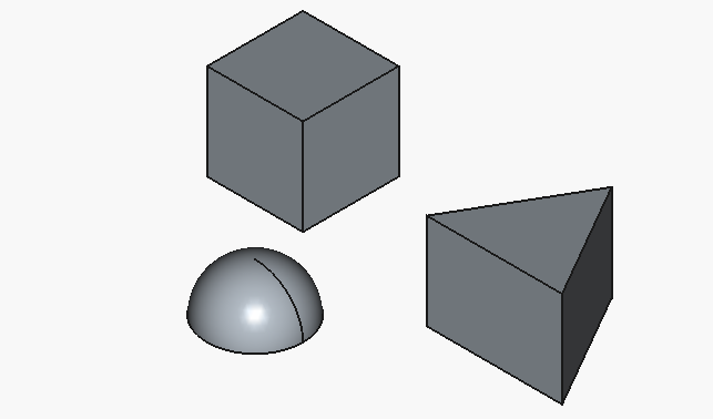
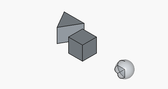
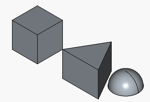
Aaand here’s how the result looks like:
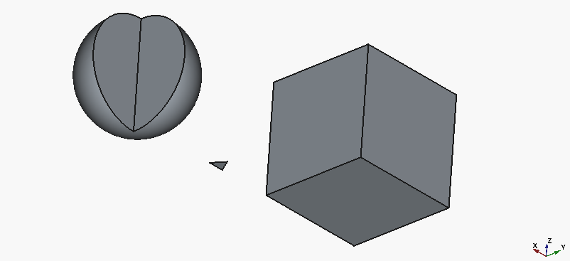
openscad smoke 1

Well, we actually got working code, and that’s good…​ but only the cube looks half-way close to what we intended. To be fair, the triangle is on us, as we specified the parameters for a 3D object as if it was 2D.

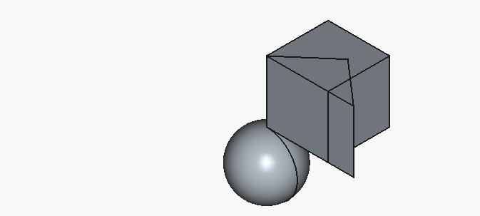
Let’s give ChatGPT another go, with the following correction:

The triangle is considerably too small, and the half-sphere renders as a full sphere within a cube. Please fix.

The "full sphere with a block" description actually refers to the presentation before a "cut" operation.

We obtain the following, supposedly corrected code:

Here’s a corrected OpenSCAD file: The triangle now has a more visible size (side length increased to 10mm). The half-sphere is properly rendered by subtracting the lower half of the sphere.

// Cube with size 10mm
translate([0, 0, 0])
cube(10);

// Regular triangle with side 10mm
module regular_triangle(side) {
    h = side * sqrt(3) / 2;
    polygon(points=[
        [0, 0],
        [side, 0],
        [side/2, h]
    ]);
}
translate([15, 0, 0])
regular_triangle(10);

// Half-sphere of radius 5mm
difference() {
    translate([30, 5, 5])
    sphere(r=5, $fn=64);
    // Cut off the bottom half
    translate([25, 0, 5])
    cube([10, 10, 5], center=false);
}

The triangle is now clearly visible. The half-sphere is created by subtracting a cube from the bottom half of the sphere.

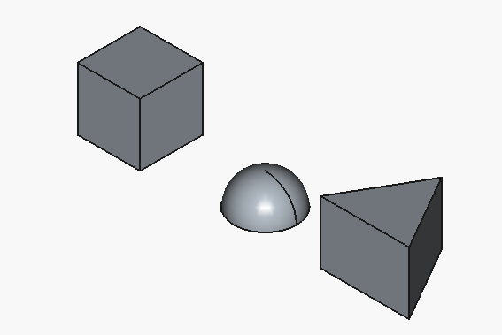
resulting in:
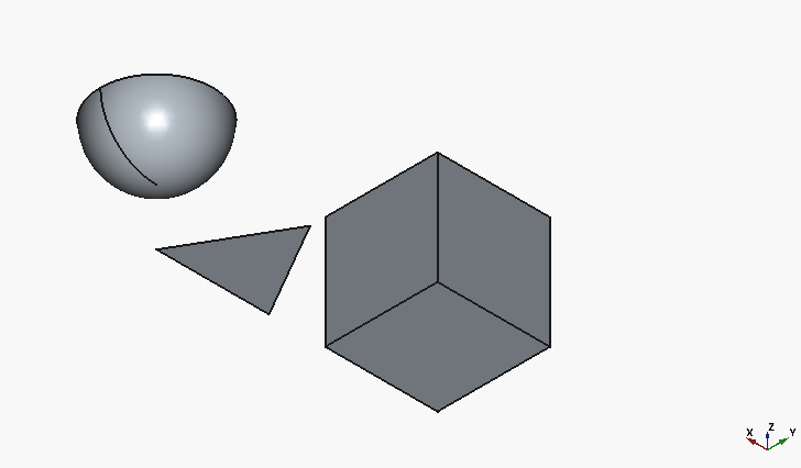
openscad smoke 2

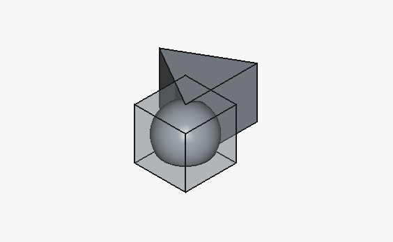
Much better, although, with all the hype towards the big-player LLMs, I would have expected for the half-sphere to be at least oriented with the flat face downwards.

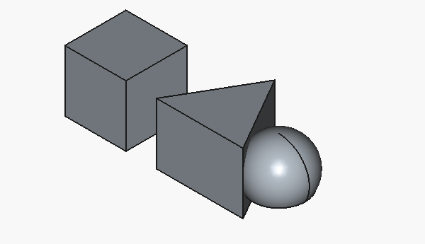
Anyway, after asking once more:

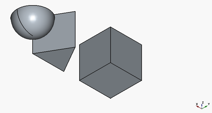
Have the triangle extrude upwards with a face height of 10mm.

We can see the following:
openscad smoke 3

Let’s try to form a refined prompt that will get us to our target in one go:

Create an OpenSCAD file that encodes the following:

  • a cube with a size of 10mm,

  • an extruded solid with a base consisting of a regular triangle with a side of sqrt(2)*10mm, and an extrusion height of 10mm,

  • a half-sphere of radius 5mm, with the flat side facing downwards, and located at the origin of the Z axis.

The response is:

Here is an OpenSCAD file that creates the requested shapes, positioned to avoid overlap: Explanation: The cube is placed at the origin. The extruded triangle uses linear_extrude for a 3D solid, with the triangle base sized as specified. The half-sphere is created by subtracting the lower half of a sphere, with the flat face on the XY plane at Z=0.

// Cube with size 10mm
translate([0, 0, 0])
cube(10);

// Extruded regular triangle (side = sqrt(2)*10mm, height = 10mm)
module regular_triangle(side) {
    h = side * sqrt(3) / 2;
    polygon(points=[
        [0, 0],
        [side, 0],
        [side/2, h]
    ]);
}
translate([20, 0, 0])
linear_extrude(height=10)
regular_triangle(sqrt(2)*10);

// Half-sphere of radius 5mm, flat side down at Z=0
difference() {
    translate([40, 5, 5])
    sphere(r=5, $fn=64);
    // Remove lower half
    translate([35, 0, 0])
    cube([10, 10, 5], center=false);
}

This will generate the three shapes as described, each separated along the X axis.

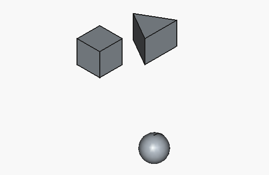
And the code renders to the following:
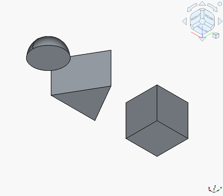
openscad smoke final prompt

That looks about like something we wanted.

Baselines

Having established a baseline prompt, let’s run some tests comparing different LLMs. The selection of models stems from both what is available through Copilot, and what is currently thought of as "good" local LLMs tailored for code generation.

The latter was produced through an extremely rigorous and formal approach of an ensemble method composed of the result of a deep research query based on the currently expressed trends in the prosumer space, validated by a cross-reference from the immediately available wetware compute&storage system instance.

In other words: I ran the query on last month’s posts in r/LocalLLaMA and checked it wasn’t BS ,compared to my own impressions.

Local model selection

The models we’re going to use here are all unsloth’s quantizations/optimizations, specifically (name: variant):

As far as configuration goes:

  • everything runs through llama.cpp (with llama-swap for convenience),

  • for every model, the context window size is 16k (mostly for a "thinking buffer"),

  • --jinja (unsloth’s suggested pre-prompts) is enabled wherever recommended in the model card.

A final clarification: the specific choice of quantization originates from the goal of all models fitting in roughly the same amount of VRAM (under 48 GB). This is theoretically not strictly "fair"[2], but, firstly, it matches actual usage scenarios better, and modern larger models often exhibit surprisingly good performance even with more aggressive quantizations anyway.

Setup

Now, back to our tests. For each model, we’ll do best of three, and show just that.

Some visualizations include solids that are translucent. This is a manual toggle for visualization purposes, i.e. not an artifact of the model output.
Model Cube Triangle Extrude Half-sphere Visualization Notes

GPT-4.1

openscad base gpt41

-

GPT-5 mini

openscad base gpt5mini

Needed retries.

Claude Sonnet 4.5

openscad base claude45

Insufficient spacing.

Gemini 2.5 Pro

openscad base gemini25pro

Better presentation, clean code, included smoothing.

Gemini 2.0 Flash

openscad base gemini20flash

Insufficient spacing.

Qwen3-Coder-30B-A3B

openscad base qwen3 coder

The sphere is cut, but at the wrong height. Insufficient spacing.

GLM-4.5-Air

openscad base glm 4.5 air

Strong overlap.

Devstral Small 2507

openscad base devstral small 2507

-

GPT-OSS 20B

openscad base gptoss20b

The half-sphere cut is present, but incorrectly offset.

Overall, most "full" cloud models managed to get everything right spec-wise, and included some sensible formatting. On the other hand, local models struggled with the half-sphere more often than not, with only GLM-4.5-Air managing to get it right.

It would be unfair not to mention that our setup is relatively brutal towards local models. There’s no fine-tuning, no prompt engineering beyond the base prompt, or other methods to wring more of them. Even a follow-up query to check "their work" for errors results in better output. Nevertheless, I’d argue the comparisons actually demonstrate how good current local models are.

Right, let’s proceed to the next experiment…​ just joking, of course we’re going to print the results!

From matrix multiplication to plastic strings

Let’s take GLM 4.5-Air’s output as an example. This is the code:

// Cube of size 10mm
cube(10);

// Extruded triangular prism with base sqrt(2)*10mm and height 10mm
s = sqrt(2) * 10;
h = (sqrt(3)/2) * s;
points = [
    [0, h * 2/3],
    [-s/2, -h/3],
    [s/2, -h/3]
];
linear_extrude(height=10) polygon(points);

// Half-sphere (hemisphere) of radius 5mm with flat face downward
difference() {
    sphere(r=5, $fn=20);
    translate([0,0,-5]) cube(10, center=true);
}

This is the initial rendering (in FreeCAD):
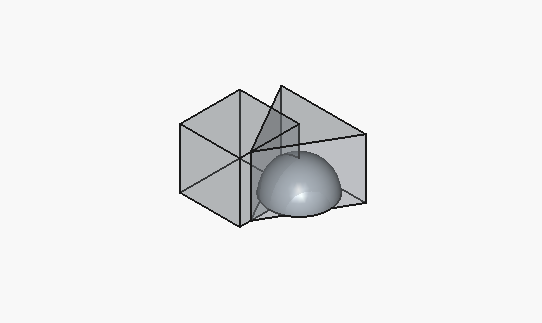
openscad base glm 4.5 air

This is the print timelapse[3]:

And this is the result, printed at a "rough" 0.3mm layer height – usually reserved for functional parts – in white PLA:
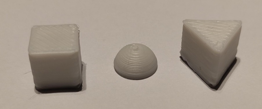
smoke print photo
Figure 3. Something something late 90s video game publisher slogan

Kinda' cool, right?

Practical prints

Design

We’ve gone through a simple scenario for initial validation. Now, onto something more practical.

3D printing, specifically FDM/FFF printing, offers some unique opportunities not present in other manufacturing methods. One of these is the ability to create intrinsically enclosed and/or enmeshed multimaterial assemblies. During the print process, we can pause at specific layers, and add/mount subcomponents providing additional capabilities.

And you know what’s annoying? When you need to assemble something – like a piece of furniture – you have your set of screws, bolts, or other small elements…​ so you lay them out in a more or less organized fashion. But then, then your concentration gets broken, you need to get up to retrieve something, and you (or a less or more small furry critter you house, you didn’t notice coming in) end up kicking said small things all over the place.

Which leads to the following project: a small tray with several compartments, and, critically, embedded magnets in the compartment floors – to hold the aforementioned screws, etc. down.

This time, we’re going to try both cloud and local models, but now more informally, with a limited selection, and allowing for some corrections.

Keeping things more concise, what follows is the prompt that resulted in the best initial results:

Create an OpenSCAD file that encodes a 50 mm by 50 mm tray divided into four compartments. The divider and external walls of the tray must be 5mm tall and 1.2mm wide. The base of the tray should be at least 3 mm thick, and include voids able to accommodate 4mm x 10mm x 2 mm magnets. The voids should be placed at the center of each compartment, and be no farther away than 0.6mm from the top surface of the base of the tray.

Claude Sonnet (3.7 Thinking) produced an interesting case, i.e. two solids:
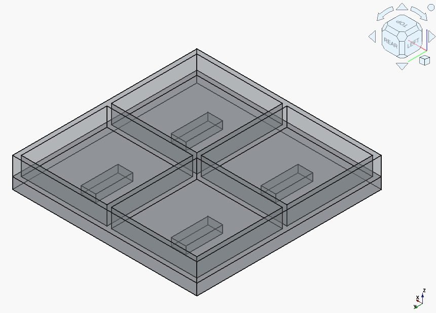
openscad tray claude37t
Figure 4. (gist)

Gemini 2.5 Pro needed to correct a syntax error, but produced a single solid with proper magnet holes:
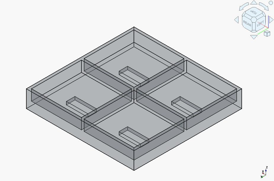
openscad tray gemini25pro
Figure 5. (gist)

GPT-4.1 generated a curious abberation, with some elements clearly inverted compared to what they should be:
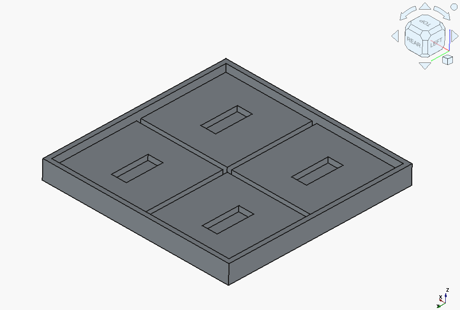
openscad tray gpt41
Figure 6. (gist)

But after a couple of followups, it got there.
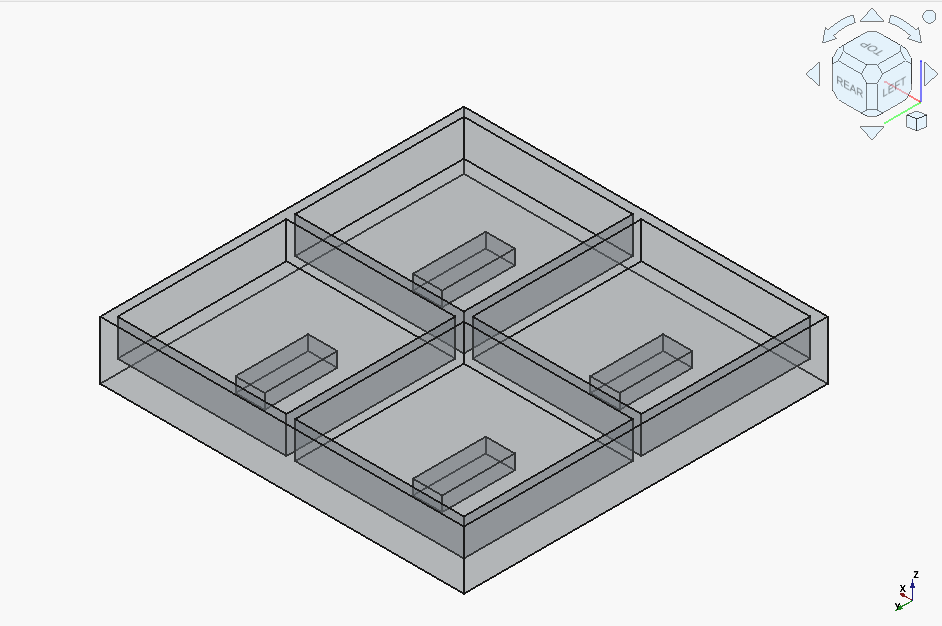
openscad tray gpt41 fixed
Figure 7. (gist)

Now onto the local models. gpt-oss-20b actually got it right on the first try – outshining the cloud’s Claude 3.5 !
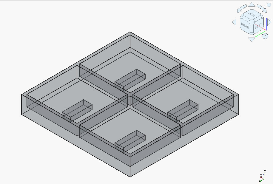
openscad tray gptoss20b
Figure 8. (gist)

Qwen3-Coder-30B-A3B got off to a rocky start:
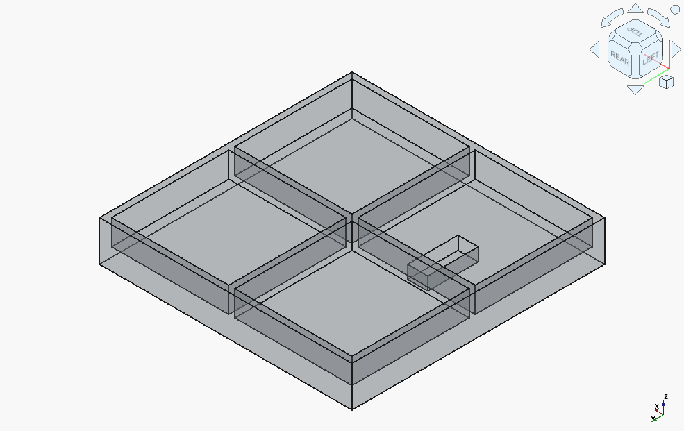
openscad tray qwen3 coder
Figure 9. (gist)

It finally turned around, after almost hitting the context window limit, needing to be explicitly told what one major issue is (incorrect assumption for the location of the coordinate origin), and needed to be kept reminded not to introduce "magic numbers".
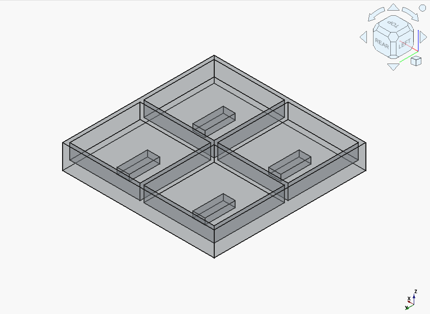
openscad tray qwen3 coder fixed
Figure 10. (gist)

Devstral got it so completely wrong that it’s difficult to say where to start:
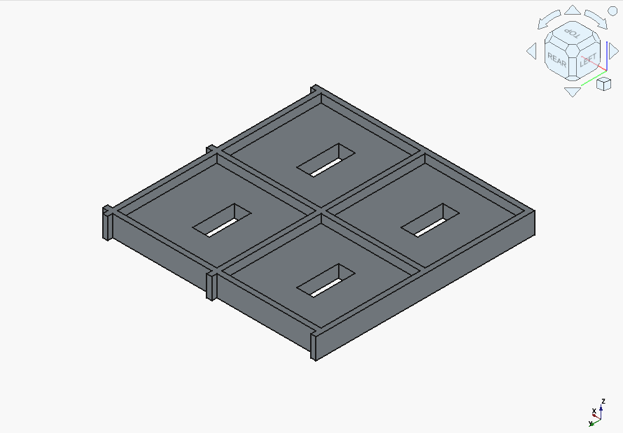
openscad tray devstral small 2507
Figure 11. (gist)

However, it only took two followups to get the correct solid. And unlike Qwen3-Coder, Devstral immediately acted on the feedback about the Z offset for the magnet pockets being incorrect.

GLM 4.5 Air is a funny case. The first result was completely wrong:
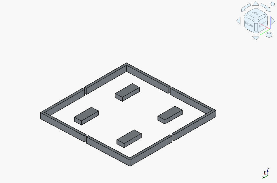
openscad tray glm 4.5 air
Figure 12. (gist)

and it didn’t manage to produce a sensible fix before running out of context window. It appeared to code in everything but the base as a void, and got stuck on that.

…​but got it the model completely right on the very second try:
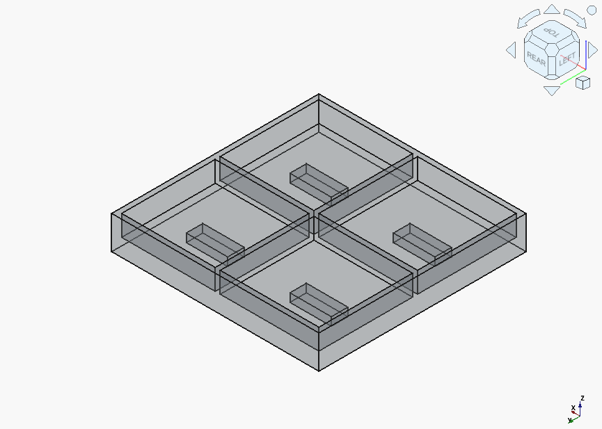
openscad tray glm 4.5 air iter
Figure 13. (gist)

Implementation

Theoretically, we’re now ready to put the models in the slicer and print something out. Practically, there is a problem, which I’m sure any reader with some experience in FFM manufacture has already noticed.

Let’s cut to the chase: none of the designs provide any allowance for:

  • the installed magnets having anything else than the provided dimensions,

  • the print itself actually not holding its desired dimensions.

The above is actually quite damning: handling tolerances is fundamental not only to 3D printing, but any manufacturing process. Barring some Angstrom-level nanofabrication[4], nothing fits precisely. And don’t get me wrong: modern consumer 3D printers offer a crazy level of precision for their purchase price. Still, when 0 mm precision implies 1e-5 mm clearance, that’s still that many moles of plastic or metal that need to fit somewhere. Sure, most materials provide some give, but there’s a limit.

The choice of magnets as our inclusion into the gem we’re creating was quite intentional. Magnets introduce their own particular problems in 3D printing, for the virtue of being what they are. If the print bed attracts the magnets well enough (and many bed surfaces are actually magnetized), there’s the risk of the magnet ripping off the bottom layers of the object as its being removed. And if the printer’s toolhead’s nozzle is attractive to the magnet enough…​ congratulations, you’ve earned an achievement of a relative exotic print failure, possibly with physical printer damage.

Back in the context of LLMs, all of the above highlights one of their major flaws: their lack of perceived "understanding" of various intricacies of problem domains – usually followed by some variation of "Of course, I completely […​]" and assorted simulated self-flagellation (actual course correction not guaranteed).

The flipside of the above is that chat-specialized LLMs can and do correct themselves, even with vague prompts. And, for example, Claude[5] did exactly that, provided a prompt to correct its original output:

Review the provided code for any possible tweaks that are required, or recommended, for a 3D print of the object to succeed. Apply those tweaks to the original code, while still preserving the validity of it with respect to the original spec.

// Tray with 4 compartments and magnet voids
// Dimensions: 50mm x 50mm

// Parameters
tray_width = 50;
tray_length = 50;
wall_height = 5;
wall_thickness = 1.2;
base_thickness = 3;

magnet_width = 4;
magnet_length = 10;
magnet_height = 2;
magnet_offset_from_top = 0.6;

// Print tolerances
magnet_tolerance = 0.15; // Added clearance for easier magnet insertion
chamfer_size = 0.3; // Chamfer at void opening

// Calculate internal dimensions
inner_width = tray_width - 2 * wall_thickness;
inner_length = tray_length - 2 * wall_thickness;
compartment_width = (inner_width - wall_thickness) / 2;
compartment_length = (inner_length - wall_thickness) / 2;

module magnet_void_with_chamfer() {
    // Main void with tolerance
    cube([magnet_width + magnet_tolerance, magnet_length + magnet_tolerance, magnet_height + 0.1]);

    // Chamfer at opening
    translate([0, 0, magnet_height])
    linear_extrude(height = chamfer_size, scale = [(magnet_width + magnet_tolerance + 2*chamfer_size)/(magnet_width + magnet_tolerance), (magnet_length + magnet_tolerance + 2*chamfer_size)/(magnet_length + magnet_tolerance)])
    translate([0, 0, 0])
    square([magnet_width + magnet_tolerance, magnet_length + magnet_tolerance]);
}

module base() {
    difference() {
        // Base plate
        cube([tray_width, tray_length, base_thickness]);

        // Magnet voids in each compartment
        // Top-left
        translate([
            wall_thickness + compartment_width/2 - (magnet_width + magnet_tolerance)/2,
            wall_thickness + compartment_length/2 - (magnet_length + magnet_tolerance)/2,
            base_thickness - magnet_height - magnet_offset_from_top
        ])
        magnet_void_with_chamfer();

        // Top-right
        translate([
            wall_thickness + compartment_width + wall_thickness + compartment_width/2 - (magnet_width + magnet_tolerance)/2,
            wall_thickness + compartment_length/2 - (magnet_length + magnet_tolerance)/2,
            base_thickness - magnet_height - magnet_offset_from_top
        ])
        magnet_void_with_chamfer();

        // Bottom-left
        translate([
            wall_thickness + compartment_width/2 - (magnet_width + magnet_tolerance)/2,
            wall_thickness + compartment_length + wall_thickness + compartment_length/2 - (magnet_length + magnet_tolerance)/2,
            base_thickness - magnet_height - magnet_offset_from_top
        ])
        magnet_void_with_chamfer();

        // Bottom-right
        translate([
            wall_thickness + compartment_width + wall_thickness + compartment_width/2 - (magnet_width + magnet_tolerance)/2,
            wall_thickness + compartment_length + wall_thickness + compartment_length/2 - (magnet_length + magnet_tolerance)/2,
            base_thickness - magnet_height - magnet_offset_from_top
        ])
        magnet_void_with_chamfer();
    }
}

module walls() {
    // Outer walls
    difference() {
        cube([tray_width, tray_length, wall_height + base_thickness]);
        translate([wall_thickness, wall_thickness, base_thickness])
        cube([inner_width, inner_length, wall_height + 1]);
    }

    // Horizontal divider
    translate([wall_thickness, tray_length/2 - wall_thickness/2, base_thickness])
    cube([inner_width, wall_thickness, wall_height]);

    // Vertical divider
    translate([tray_width/2 - wall_thickness/2, wall_thickness, base_thickness])
    cube([wall_thickness, inner_length, wall_height]);
}

// Render the complete tray
base();
walls();

Summarized as:

Key improvements:

  • Magnet voids now 0.15mm larger for press-fit tolerance

  • Chamfered openings prevent filament strings and ease magnet insertion

  • All dimensions preserved per original spec

  • Print-friendly geometry maintained

That is an improvement, although one gripe remains in the tolerance size, usually dependent on the layer thickness.

A surprising outcome is the addition of chamfers: on this scale, will do sweet FA, but it shows the relevant embeddings for general 3D printing improvements are present.

Let us revert to local models. For GLM 4.5 Air, the model did attempt to make the output better:

Key Improvements for 3D Printability:

  • Base Thickness Increase:

    • Increased from 3mm to 4mm to provide more material below magnet voids

    • Ensures 1.4mm material below voids (vs. 0.4mm in original) for structural integrity

    • Still meets "at least 3mm" specification requirement

  • Magnet Void Positioning:

    • Voids now start at z=1.4mm (previously z=0.4mm) in a 4mm base

    • Maintains 0.6mm clearance from top surface

    • Preserves exact 4x10x2mm magnet dimensions

  • Structural Enhancements:

    • Eliminated thin-walled sections below magnets that would be prone to breakage

    • Maintained all original dimensional specifications

    • Kept wall thickness at 1.2mm (suitable for FDM printing)

  • Print Orientation Recommendations:

    • Print with base down (as modeled)

    • Supports should be added for internal divider bases if needed

    • Print at 0.2mm layer height for detail retention

  • Material Considerations:

    • Total height now 9mm (4mm base + 5mm walls)

    • Maintains compartment size (25x25mm) and wall thickness (1.2mm)

    • Preserves exact 50x50mm external dimensions

You’ll note the conspicuous lack of tolerance factors for the magnet voids.

Giving it more of a hint:

These are good, but miss one aspect. Here’s a hint: when inserting objects into a 3D print, are they generally the exact size specified, and are the voids in the print also of that exact size?

Using the hint, apply tweaks to the provided code, while still preserving the validity of it with respect to the original spec.

provides us with:

// Tray dimensions
tray_width = 50;    // mm
tray_length = 50;   // mm
tray_height_base = 4;  // Increased from 3mm for strength
wall_thickness = 1.2;  // mm
wall_height = 5;       // mm
compartment_size = tray_width / 2;  // 25mm each

// Magnet dimensions with tolerance for insertion
magnet_width = 4;    // mm
magnet_length = 10;  // mm
magnet_height = 2;   // mm
magnet_tolerance = 0.2;  // Added tolerance per dimension
magnet_depth_offset = 0.6;  // mm from top of base

// Effective magnet void dimensions (with tolerance)
void_width = magnet_width + 2 * magnet_tolerance;
void_length = magnet_length + 2 * magnet_tolerance;
void_height = magnet_height + magnet_tolerance;  // Only add tolerance to depth

// Calculate positions for magnet voids
magnet_x = compartment_size / 2 - magnet_length / 2;
magnet_y = compartment_size / 2 - magnet_width / 2;
magnet_z = tray_height_base - magnet_depth_offset - magnet_height;

// Generate the tray
difference() {
    // Base and walls combined
    union() {
        // Base (now 4mm thick)
        cube([tray_width, tray_length, tray_height_base], center=false);

        // External walls
        translate([0, 0, tray_height_base])
            cube([wall_thickness, tray_length, wall_height]);          // Left wall
        translate([tray_width - wall_thickness, 0, tray_height_base])
            cube([wall_thickness, tray_length, wall_height]);          // Right wall
        translate([0, 0, tray_height_base])
            cube([tray_width, wall_thickness, wall_height]);          // Bottom wall
        translate([0, tray_length - wall_thickness, tray_height_base])
            cube([tray_width, wall_thickness, wall_height]);          // Top wall

        // Internal dividers
        translate([compartment_size, 0, tray_height_base])
            cube([wall_thickness, tray_length, wall_height]);          // Vertical divider
        translate([0, compartment_size, tray_height_base])
            cube([tray_width, wall_thickness, wall_height]);          // Horizontal divider
    }

    // Magnet voids in each compartment (with tolerance)
    // Bottom-left
    translate([magnet_x - magnet_tolerance, magnet_y - magnet_tolerance, magnet_z])
        cube([void_length, void_width, void_height]);

    // Bottom-right
    translate([magnet_x + compartment_size - magnet_tolerance, magnet_y - magnet_tolerance, magnet_z])
        cube([void_length, void_width, void_height]);

    // Top-left
    translate([magnet_x - magnet_tolerance, magnet_y + compartment_size - magnet_tolerance, magnet_z])
        cube([void_length, void_width, void_height]);

    // Top-right
    translate([magnet_x + compartment_size - magnet_tolerance, magnet_y + compartment_size - magnet_tolerance, magnet_z])
        cube([void_length, void_width, void_height]);
}

The model outputs a suboptimal result, in that it quasi-hallucinates the tolerance values w.r.t. height. Nevertheless, and unlike the cloud-based model, it potentially corrects for both aspects of magnet inclusion in 3D prints.

And here’s gpt-oss' result:

//============================================================
//  50 × 50 mm Tray with 4 compartments
//  Walls: 5 mm tall, 1.2 mm wide
//  Base: 3 mm thick
//  Magnet voids (4 × 10 × 2 mm) – centred in each compartment
//  Void top is 0.6 mm from the top of the base
//============================================================

//---------------------------
//  Parameters
//---------------------------
tray_size      = 50;      // overall tray size (mm)
wall_thickness = 1.2;     // wall thickness (mm) – thin for FDM, keep spec
wall_height    = 5;       // wall height (mm)
base_thickness = 3;       // base thickness (mm)

magnet_size      = [4, 10, 2];   // [x, y, z] size of the magnet void (mm)
magnet_depth_top = 0.6;          // distance from top of base to top of void (mm)
magnet_z_bottom  = base_thickness - magnet_depth_top - magnet_size[2]; // z of void bottom (mm)

//---------------------------
//  Helper modules
//---------------------------
/// Draws a single magnet void at the given centre point
module magnet_void(centre) {
    translate([ centre[0] - magnet_size[0]/2,
                centre[1] - magnet_size[1]/2,
                magnet_z_bottom ])
        cube( magnet_size );
}

/// Base of the tray – 50 × 50 × 3 mm – with the four voids subtracted
module base_with_voids() {
    difference() {
        color("lightgrey")  // base colour (preview only)
            cube([tray_size, tray_size, base_thickness]);

        // centres of the four compartments
        centres = [
            [12.8, 12.8],   // bottom‑left
            [37.2, 12.8],   // bottom‑right
            [12.8, 37.2],   // top‑left
            [37.2, 37.2]    // top‑right
        ];

        for (c = centres)
            magnet_void(c);          // subtract the void
    }
}

/// Outer walls – 5 mm tall, 1.2 mm thick, positioned on top of the base
module outer_walls() {
    difference() {
        translate([0, 0, base_thickness])  // walls start on top of base
            color("tan")  // wall colour (preview only)
                cube([tray_size, tray_size, wall_height]);

        translate([wall_thickness, wall_thickness, base_thickness])
            cube([ tray_size - 2*wall_thickness,
                   tray_size - 2*wall_thickness,
                   wall_height ]);
    }
}

/// Two internal divider walls (vertical + horizontal)
module divider_walls() {
    // vertical divider – centred at x = 25 mm
    translate([ 25 - wall_thickness/2,
                wall_thickness,
                base_thickness ])
        color("tan")
            cube([ wall_thickness,
                   tray_size - 2*wall_thickness,
                   wall_height ]);

    // horizontal divider – centred at y = 25 mm
    translate([ wall_thickness,
                25 - wall_thickness/2,
                base_thickness ])
        color("tan")
            cube([ tray_size - 2*wall_thickness,
                   wall_thickness,
                   wall_height ]);
}

//---------------------------
//  Assemble the tray
//---------------------------
union() {
    base_with_voids();
    outer_walls();
    divider_walls();
}

While it did provide a significantly streamlined code (unprompted bells and whistles included), it also still needed an explicit reminder about the precision issue before it outputted a model with tolerances taken into account.

Right, let’s get to the printing.

Results

We’ll take the GLM 4.5 Air model for the print, with the following changes:

  • slightly adjusting:

    • the numerical values for the tolerance,

    • the offset from the top,

    • and the thickness of the base;

  • adding an additional z clearance to the magnet void height;

  • and fixing the void_height calculation, which should also be based on magnet_depth_offset.

The base thickness and top offset changes, or rather, the need for them, became apparent when it turned out that the currently-used nozzle is significantly more magnetic than expected – so the magnets need to be nested deeper into the print, which will make them hopefully attracted more to the printbed than to the nozzle.

// Tray dimensions
tray_width = 50;    // mm
tray_length = 50;   // mm
tray_height_base = 6;  // Increased from 3mm for strength
wall_thickness = 1.2;  // mm
wall_height = 5;       // mm
compartment_size = tray_width / 2;  // 25mm each

// Magnet dimensions with tolerance for insertion
magnet_width = 4;    // mm
magnet_length = 10;  // mm
magnet_height = 2;   // mm
magnet_tolerance = 0.6;  // Added tolerance per dimension
magnet_z_clearance = 2.1;  // Additional clearance in height
magnet_depth_offset = 0.6;  // mm from top of base

// Effective magnet void dimensions (with tolerance)
void_width = magnet_width + 2 * magnet_tolerance;
void_length = magnet_length + 2 * magnet_tolerance;
void_height = magnet_height + magnet_tolerance + magnet_z_clearance;  // Only add tolerance to depth

// Calculate positions for magnet voids
magnet_x = compartment_size / 2 - magnet_length / 2;
magnet_y = compartment_size / 2 - magnet_width / 2;
magnet_z = tray_height_base - void_height - magnet_depth_offset;

// Generate the tray
difference() {
    // Base and walls combined
    union() {
        // Base (now 4mm thick)
        cube([tray_width, tray_length, tray_height_base], center=false);

        // External walls
        translate([0, 0, tray_height_base])
            cube([wall_thickness, tray_length, wall_height]);          // Left wall
        translate([tray_width - wall_thickness, 0, tray_height_base])
            cube([wall_thickness, tray_length, wall_height]);          // Right wall
        translate([0, 0, tray_height_base])
            cube([tray_width, wall_thickness, wall_height]);          // Bottom wall
        translate([0, tray_length - wall_thickness, tray_height_base])
            cube([tray_width, wall_thickness, wall_height]);          // Top wall

        // Internal dividers
        translate([compartment_size, 0, tray_height_base])
            cube([wall_thickness, tray_length, wall_height]);          // Vertical divider
        translate([0, compartment_size, tray_height_base])
            cube([tray_width, wall_thickness, wall_height]);          // Horizontal divider
    }

    // Magnet voids in each compartment (with tolerance)
    // Bottom-left
    translate([magnet_x - magnet_tolerance, magnet_y - magnet_tolerance, magnet_z])
        cube([void_length, void_width, void_height]);

    // Bottom-right
    translate([magnet_x + compartment_size - magnet_tolerance, magnet_y - magnet_tolerance, magnet_z])
        cube([void_length, void_width, void_height]);

    // Top-left
    translate([magnet_x - magnet_tolerance, magnet_y + compartment_size - magnet_tolerance, magnet_z])
        cube([void_length, void_width, void_height]);

    // Top-right
    translate([magnet_x + compartment_size - magnet_tolerance, magnet_y + compartment_size - magnet_tolerance, magnet_z])
        cube([void_length, void_width, void_height]);
}

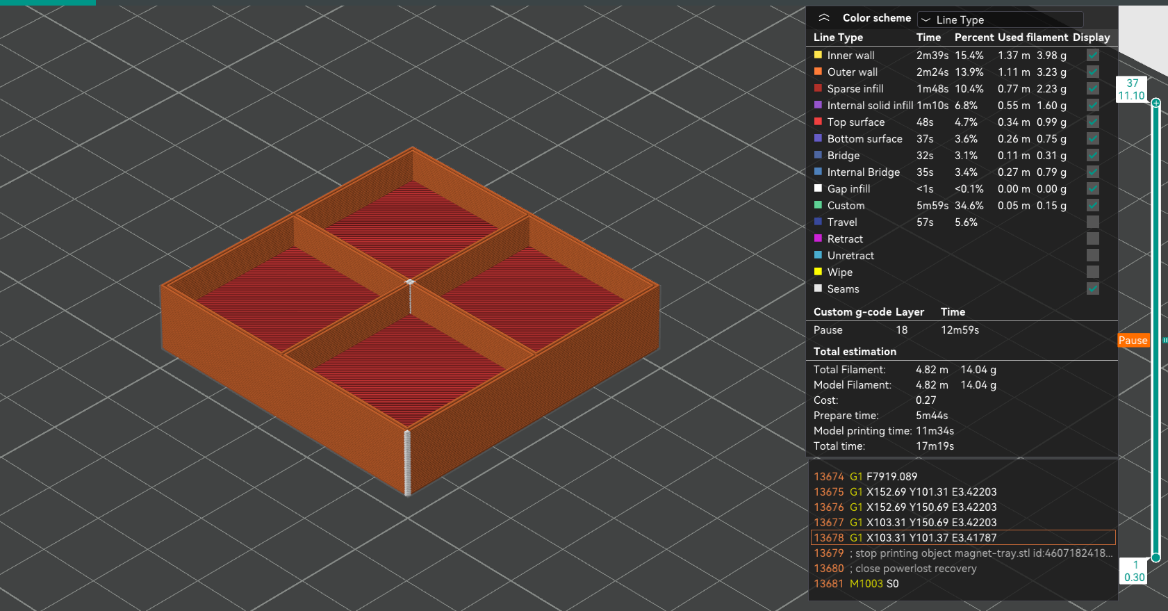
We export this code into and STL file, and examine it in the slicer:
tray print initial
Figure 14. Typical slicer program preview. The slider on the right allows to move through the layers, and the one on the bottom scrolls the printer nozzle’s simulated position within a layer.

Here’s how the layer transitions look like:

Transition of the print throughout the layers. Note the legend on the right.

The magnet voids appear to be placed between layers 2 and 18 (inclusive), which, for a 0.3 mm layer height, means that there is indeed the correct amount of space. Note that is a "Pause" marker present at layer 18: this was done manually, to be able to insert the magnets without an oven-hot nozzle assembly, backed by surprisingly strong motors, hitting one’s hand at speed.

Now, what’s left is to print:
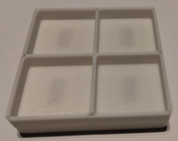
tray print photo

And does it work?

It does!

Code Review

As a final opportunity for insights, let’s go back to the various pieces of generated code, to see:

  • what can we learn about the OpenSCAD language itself,

  • what patterns are present, and how frequently they appear.

This is an area where the LLMs' usual propensity for overcommenting actually works in our favor. In general, we can see that OpenSCAD offers a set of primitives used together to formulate the final assembly. There’s also variables, and, for code organization, modules (functions).

Interestingly, for loops also exist (example, cf. tutorial, also list comprehensions), but are usually avoided, unless directly or indirectly prompted for. The net effect is the code becoming more verbose, and not actually always easier to follow. Furthermore, "unrolling" loops is the preferred style in OpenSCAD’s tutorial – which likely formed a significant part of the relevant training data available for OpenSCAD code.

The models also consistently make similar mistakes:

  • introducing "magic numbers" instead of fixing every value into a variable,

  • making "origin-related" offsetting errors,

  • "forgetting" or juxtaposing elements in the calculations (such as our GLM-4.5-Air code),

  • "fluffing up" the code with unnecessary style elements (like colors),

  • etc.

Luckily, at least at the level of complexity we’re dealing with, these mistakes are easy to spot by anyone with a half-decent eye for correctness in programs.

Outro

Hopefully, this exploration has provided not only a highlight of the fact that code-focused LLMs can generate infographics or functional 3D models, but also some measure of inspiration to check out what is also possible, without resorting to more specialized LLMs.

It is also quite interesting that even vastly simpler, local models can mostly keep up with their cloud-based counterparts, at least for this type of task.

On the flip side, the fact that everything covered here is ultimately expressed in some form of code provides a distinct advantage over typical "genAI" fare. Code can be inspected and, most importantly, easily modified, unlike, say, a typical raster image. Even the verification element is extra-useful here, as such observations can be converted into follow-up prompts to correct the output (at the risk of being you’re-absolutely-righted again).

And that’s about it for this article. I do encourage, in case anyone finds similar use cases, to share them in the comments.
1. Graphics design is my passion 🐸.
2. Neither is it completely representative of practical usage, e.g. the tokens-per-second performance varies considerably across models.
3. The solids were, of course, spaced out during the export process.
4. Yes, I do realize that’s an oxymoron, thank you very much :).
5. which I would love to say was 3.7 Thinking, but, because Copilot arbitrarily cut access to that in the meantime, was actually 4.5
Mikołaj Koziarkiewicz
gotowce splash headliner
Illustration adapted from photo by Sven Brandsma on Unsplash

Starting words

Hello again! We are continuing our series on extracting Machine Learning training data from a video game. In the previous blog entry, we’ve run some exploratory data analysis on what we aim to extract for the "final" model’s training. From now on, we’ll be focusing on the actual extraction process of said data.

The theme of this particular post is "ready-made". In other words, we’re going to look at some relatively current methods to solve our problem – or side step it; ones that have a characteristic of doing most of the work for us. We’ll start with a modern detection model, and then proceed with a local LLM (or rather, VLM), explore alternative sources of auto-derived detection training data, and compare all that with hosted LLMs from leading vendors.

The current entry is likely to be the least "technically complex" in the entire series, meaning it will be the easiest to replicate for an arbitrary person, and therefore adapt to other use cases. Something to keep in mind, especially if you, Dear Reader, stumbled upon this post randomly.

For a refresher on what we want to achieve, feel free to consult the starter blog entry, here.

Modern Detectiving with Open-Vocabulary Models

Intro

"Modern" is, of course, an ill-defined term in the current breakneck-paced bazaar of ML solutions. However, we can provide a sensible generalization of what that could be at the moment of writing of this entry, at least for our specific problem scope.

Speaking of specific, one relatively recent – i.e., no more than 2-year-old – trend for detection models is to enable operating on an "open vocabulary", as opposed to a rigid set of classes. So, instead of telling the model to detect classes of objects like "car", "bicycle", and similar, the user can be more creative, and supply prompts such as "yellow vehicle", or "car with two windows".

As already mentioned, open-vocabulary detection models have been developed for about 2 years now. A relatively fresh example, and one we’ll use in the current section, is YOLO-World, released early 2024. True to its name, it is based on YOLO for detection, augmented by the ability to fuse text and image embeddings (representations of both in a numeric vector space). A detailed explanation is beyond the scope of this blog – for those interested, the original paper is available on arXiv.

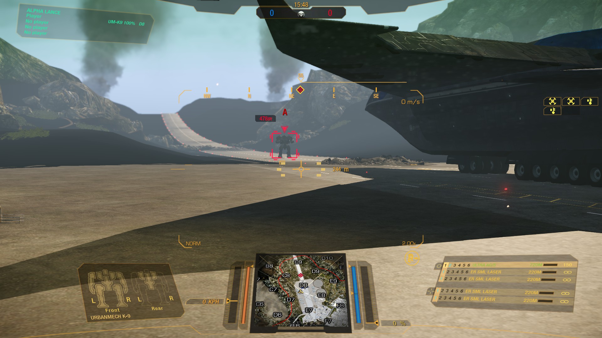
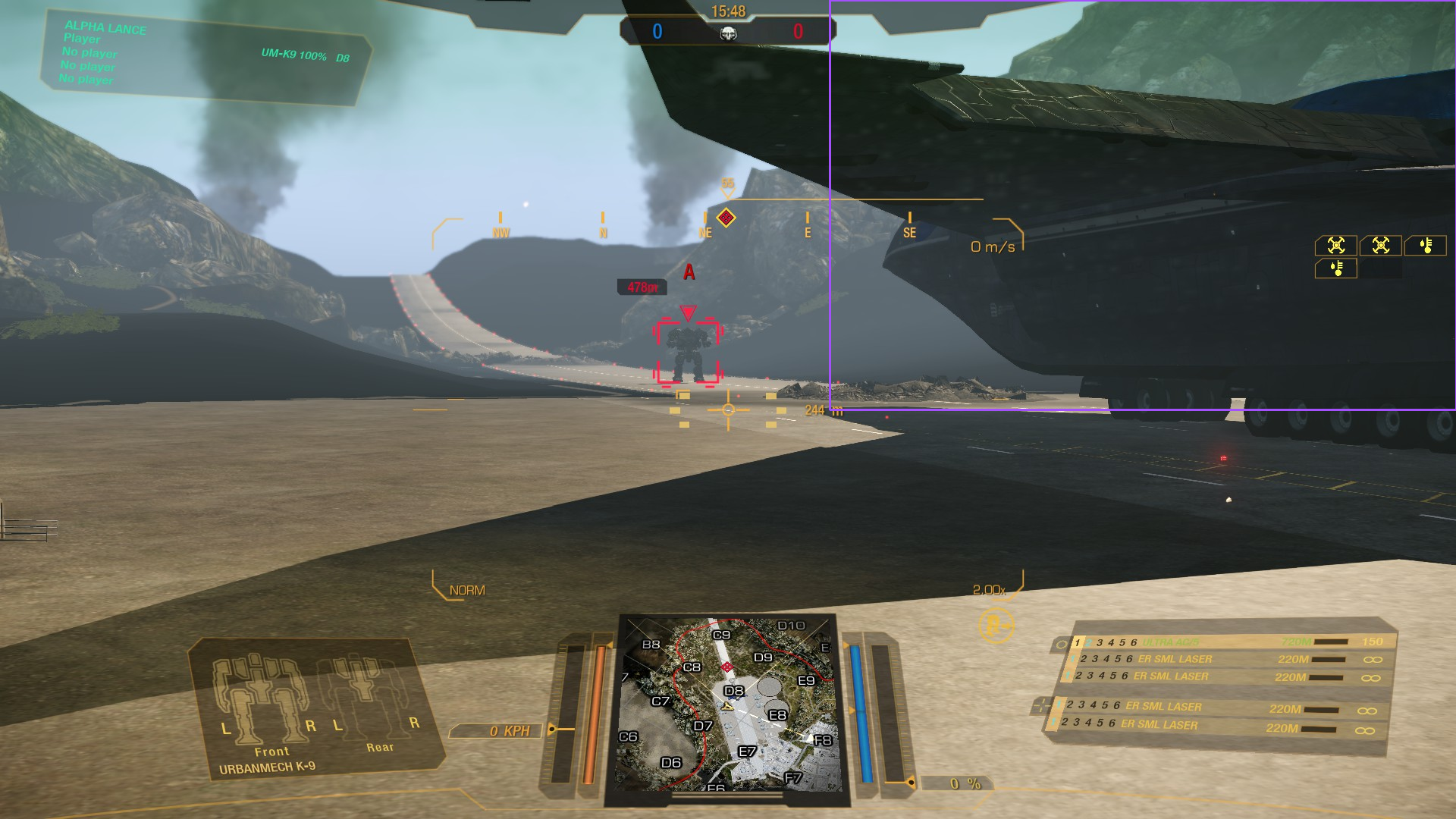
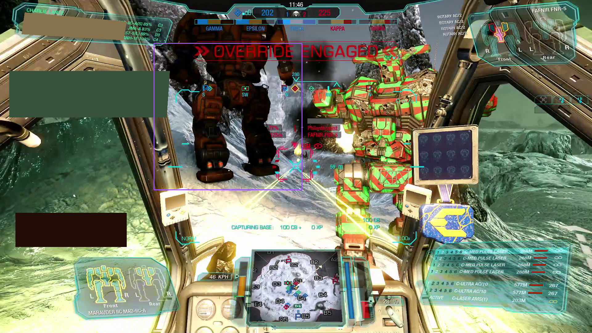
We’ll now see if we can wrangle YOLO-World to detect our designators. To juggle our memory from the earlier entries, the designator is depicted in the center of the screenshot below, surrounding the targeted mech:

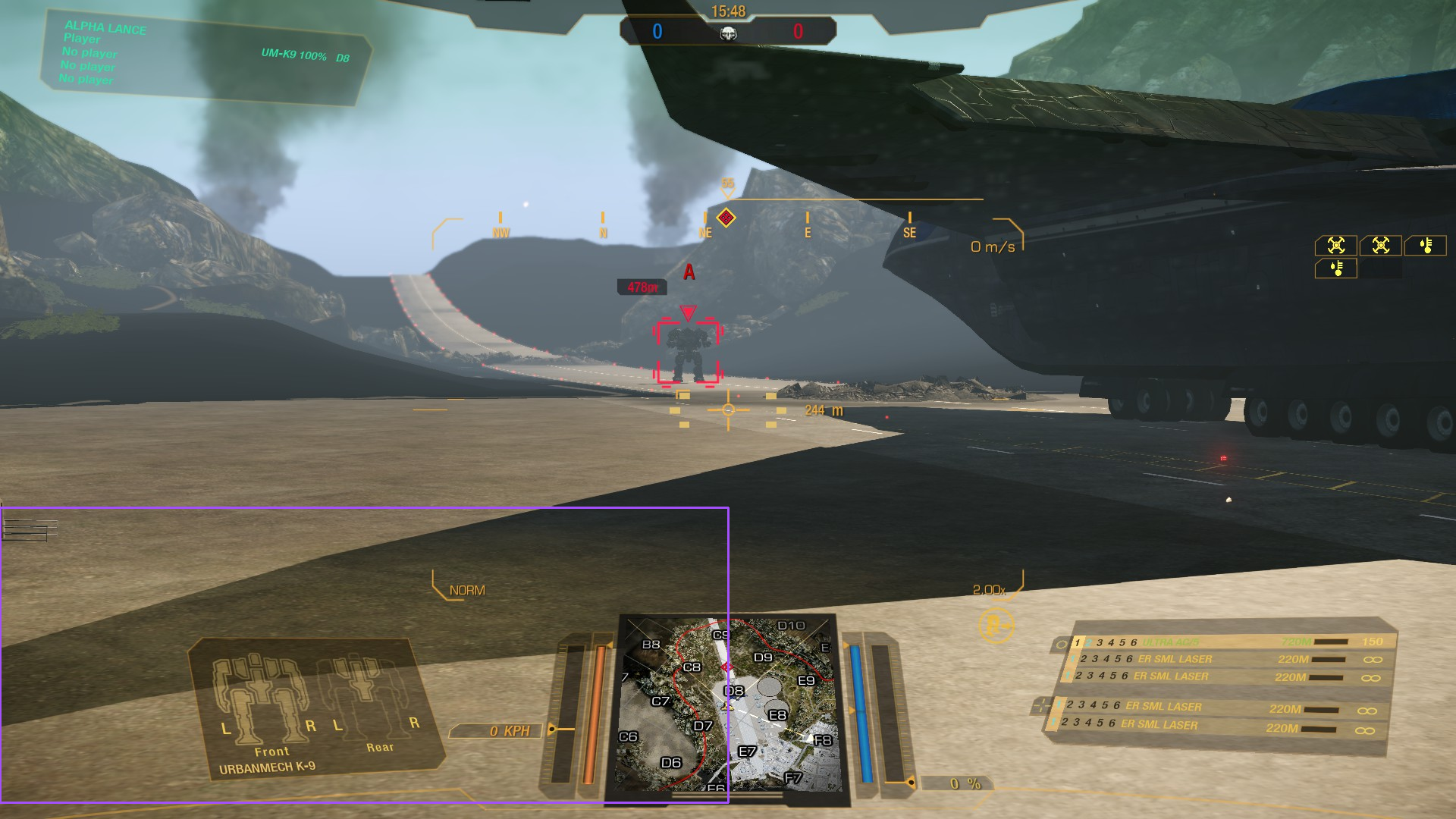
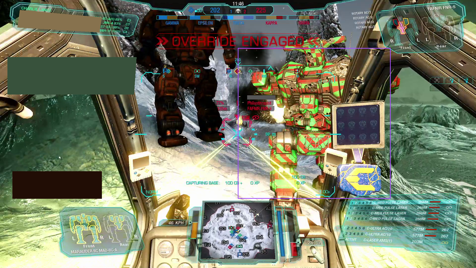
gotowce base image
Figure 1. The "base image" we’ll use for detection and similar tasks, offering a relatively uncluttered scene with both the designator and a mech clearly in view.

Implementation

The nice thing about testing out ML models in recent years is that, for the vast majority of use cases, everything is so, so convenient[1]. Not only are there repositories that standardize model usage and deployment – most prominent Hugging Face, but they often come "free" with libraries further expediting the use of models present within their ecosystem. On top of that, utility libraries exist that aggregate those "commonized" APIs for model usage, evaluation, and similar tasks into a meta-API, so that an arbitrary model authors' choice of standards is not as much of a pain point as it was, say, 5 years ago (yes, yes, feel free to add your favorite joke on standards proliferation here).

A library/framework that possesses the quality praised in the preceding paragraph, and one that we’ll be using here, is Supervision.

So let’s see how that goes; by "that" we mean using YOLO-World to find the target designator in the image. We’ll essentially be following along one of Supervision’s tutorials, with some small modifications:

import cv2 as cv
import supervision as sv
from supervision import Position

from inference.models.yolo_world.yolo_world import YOLOWorld

detection_model = YOLOWorld(model_id="yolo_world/l")

# several different class prompts, in the hope that at least
# one will match for the designator
classes = ["red rectangle", "red outline", "red box", "red designator"]

detection_model.set_classes(classes)

# setting up the annotators
BOUNDING_BOX_ANNOTATOR = sv.BoundingBoxAnnotator(thickness=2)
LABEL_ANNOTATOR = sv.LabelAnnotator(text_thickness=1, text_scale=0.5, text_color=sv.Color.WHITE, text_position=Position.BOTTOM_LEFT)

# loading the image shown above
frame = cv.imread("example_designator.jpg")

# we're using a very low confidence threshold, as we're
# interested in seeing "what sticks"
results = detection_model.infer(frame, confidence=1e-3)

# however, we are also still applying NMS, as potentially, in low
# confidence scenarios, we run the risk of being inundated with multiple,
# redundant, tiny detections
detections = sv.Detections.from_inference(results).with_nms(threshold=1e-4)

print(detections)

# will print out something like:
# Detections(xyxy=array([[     709.02,      829.93,      810.31,      1055.4],
#       [     810.56,      343.53,      879.66,      390.26],
#       [     799.74,       807.5,      1123.7,      1063.1],
#       [     809.68,      343.99,      879.36,      390.05]]),
#       mask=None,
#       confidence=array([  0.0019695,   0.0014907,   0.0012708,   0.0012423]),
#       class_id=array([2, 2, 2, 0]),
#       tracker_id=None,
#       data={'class_name': array(['red box', 'red box', 'red box', 'red rectangle'], dtype='<U13')})


# this is, again, pretty much copied from the linked tutorial
# BTW, it is a bit unusual there's no sensible
# way to compose Supervision annotators

annotated_image = frame.copy()

labels = [
    f"{classes[class_id]} {confidence:0.5f}"
    for class_id, confidence
    in zip(detections.class_id, detections.confidence)
]


annotated_image = BOUNDING_BOX_ANNOTATOR.annotate(annotated_image, detections)
annotated_image = LABEL_ANNOTATOR.annotate(annotated_image, detections, labels=labels)
sv.plot_image(annotated_image, (30, 30))

The final line results in the following image:

gotowce yolo world result sample
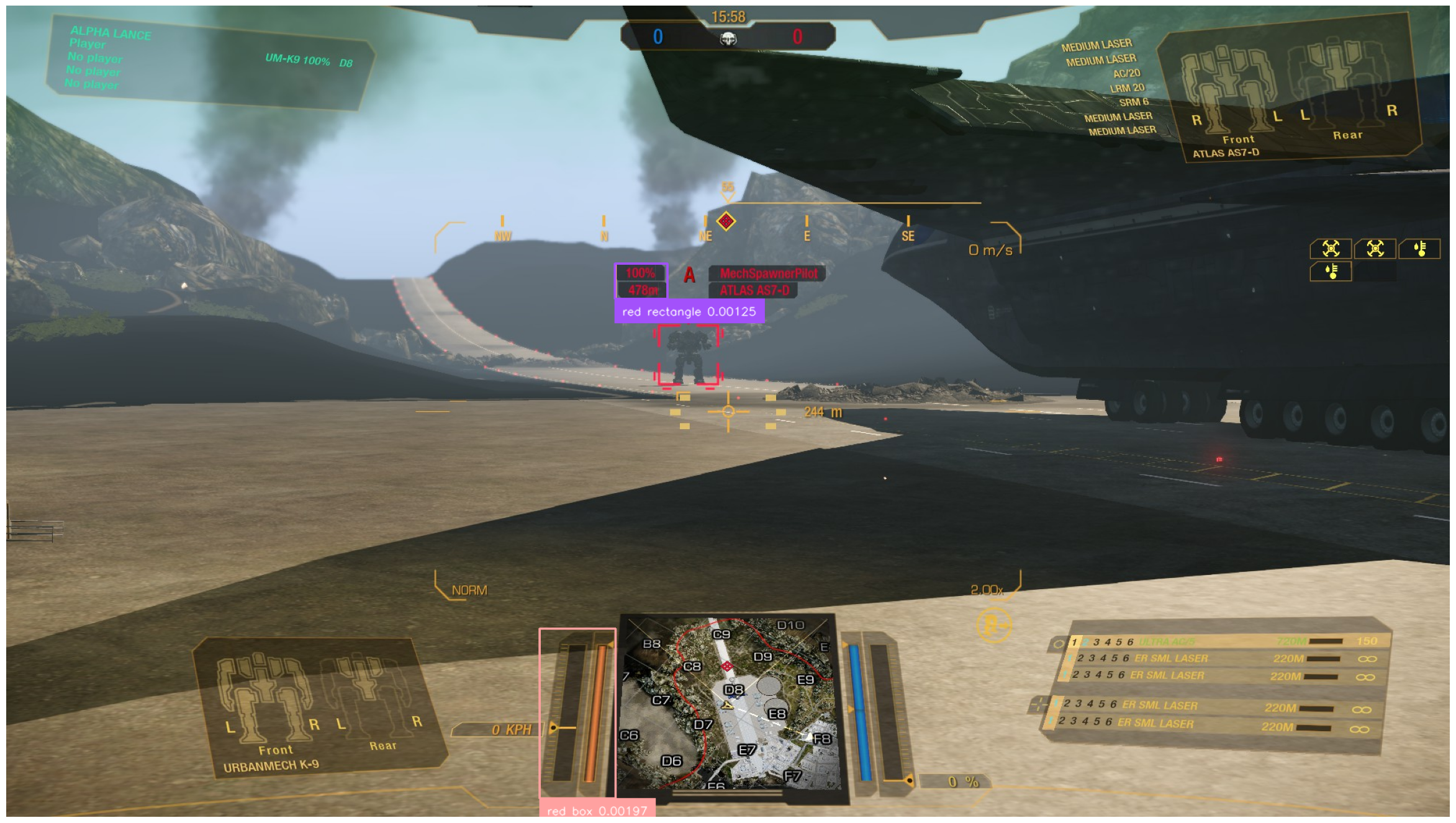
Figure 2. Results of initial YOLO-World detection attempts.

Well, that’s not looking great. The model, although powerful, evidently has trouble distinguishing various elements in our screenshot. The likely underlying reason is simple — the model was trained on datasets of "actual" images, i.e., photographs, and not on game screenshots[2].

Instead of looking at multiple (pre-)training datasets, we’ll check out the one used for evaluation, specifically LVIS. Let’s take a small look at that dataset to see what kind of text input data it provides. The spec is here – we’re interested in the "Data Format" → "Categories" section in particular. Let’s also load up the training set and see what some example data looks like. Fire up this code and read the spec in the time it takes to load:

# download the file from https://dl.fbaipublicfiles.com/LVIS/lvis_v1_train.json.zip
# and unzip it to the current directory

import pandas as pd
import json

with open("lvis_v1_train.json") as fp:
    lvis_training_instances = json.load(fp)

print(list(lvis_training_instances.keys()))
# prints out ['info', 'annotations', 'images', 'licenses', 'categories']

categories_df = pd.DataFrame(lvis_training_instances["categories"])

categories_df
gotowce yolo world training data label example
Figure 3. Example of the LVIS dataset categories.

Feel free to explore both the names and the synonyms of the categories – the latter obtainable via a snippet like the following one[3]:

category_names_synonyms = categories_df['synonyms'].explode().unique()

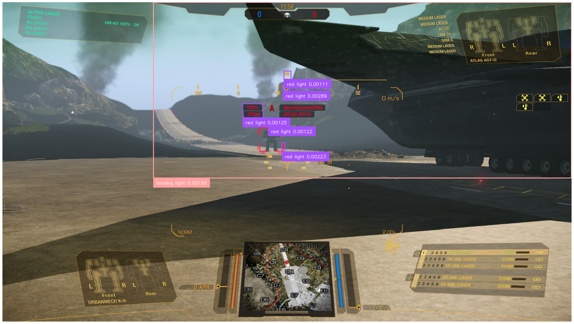
It will become quickly apparent that the problem lies in, well, the problem domain of the model – actual photographs of real-world objects. MechWarrior: Online is pretty far from being photorealistic (both due to stylistic choices and age), so the scenes in the screenshot can’t always be meaningfully interpreted by the model in the context of its training data, even down to basic visual features. Demonstrating the latter problem is the following query, attempting to capture the red landing lights visible throughout the screenshot:

classes = ["red light", "red lightbulb", "landing light"]
gotowce yolo world result sample diff query 1

None of the results remotely capture what we intended. The "big" detection is likely due to an association with a…​ related concept, which we can verify by changing the classes appropriately:

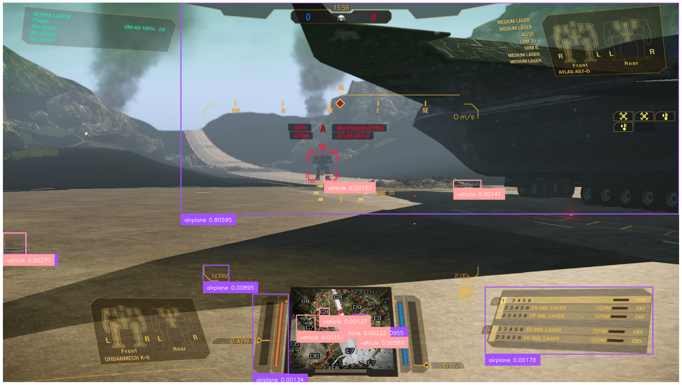
classes = ["airplane", "shuttle", "vehicle"]
gotowce yolo world result sample diff query 2

Yep, the model actually does manage to "recognize" the DropShip visible in the screenshot as an airplane[4]. Note the considerably higher confidence – 0.8 is something on the level you would expect from an "actual" detection, as opposed to the unusually low confidence we used for the investigation.

Evidently, YOLO-World is actually capable of detecting artificially generated visuals, but not what we require[5]. In fact, we’ll see similar trends with other SotA (and non-SotA) models: virtually always, training datasets include COCO, Object365, and so on. The "mainstream" models are, in general, not prepared to operate on rendered images, at least not specifically so.

So what can we do with this? One way to go is to adapt the model to our needs.

…​and this is what we would have proceeded with, had we not already declared that the blog entry will not be overtly technical. Instead, we’ll perhaps revisit the adaptation task in another entry, but, for now, we’ll just chalk this up as a lesson that even "generalist" models aren’t general enough for each and every use case – context still matters.

Local Large Models to the rescue?

Fortunately, we still have several "levels" to go up on, the first one being trying out a more powerful, but still locally runnable[6], model.

Moondream, the one we’ll use, is described as a "Vision Language Model". Its inputs are both an image, and a text prompt. The latter can be anything from a simple "describe this image" request, to "what is wrong with this specific object in the picture" quasi-anomaly-detection. In between, we have an option to request detection bounding boxes for objects described in a freeform manner, and this is what we’ll use.

As already alluded to, the model is relatively small for an LLM/VLM, and can easily be run on even a laptop-grade GPU, while still having decent time performance. The model is available on Hugging Face, which makes getting it work a breeze. Curiously, there’s little more information about it; publication-wise, the only references that can be found to the model come from comparison papers, such as this one[7].

Moondream: initial approach and examination

Regardless, let’s get right to working on it, following the example code and our test screenshot, with some small modifications:

from transformers import AutoModelForCausalLM, AutoTokenizer
from PIL import Image

# if GPU
DEVICE = 'cuda'
# uncomment if GPU insufficient
# DEVICE = None

model_id = "vikhyatk/moondream2"
revision = "2024-08-26"
model = AutoModelForCausalLM.from_pretrained(
    model_id, trust_remote_code=True, revision=revision, device_map=DEVICE
)
tokenizer = AutoTokenizer.from_pretrained(model_id, revision=revision)

base_image = Image.open('blog/img/intro_interface_demo_raw/frame_5.jpg')


def infer(image, question):
    enc_image = model.encode_image(image)
    return model.answer_question(enc_image, question, tokenizer)


print(infer(base_image, "Describe this image."))

This will give us the following:

The image shows a screenshot from a video game, featuring a player’s view of a futuristic environment with a large vehicle, mountains, and a control panel with various game elements.
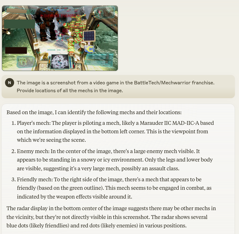
Impressive, isn’t it? Five years ago, models of this apparent analytical complexity, running on local hardware, would still be considered science-fiction.

To cut the optimistic tone somewhat, note that we have little amounting to specifics – just a general description of the scene. The output does mention the hills in the background, and a vehicle, but that’s about it.

Wait a minute 'though: maybe the "vehicle" is what we need? To figure it out, we need to write a simple function that annotates the image with bounding boxes resultant from the model’s output. And yes, the model is capable of outputting bounding box coordinates. Here’s the code:

import ast
import numpy as np
import supervision as sv

def bbox_to_annotation(image, prompt):
    bbox_str = infer(image, prompt)

    # this is unsafe in general, especially when parsing
    # open-ended model outputs! Used here for demo purposes only.
    bbox = ast.literal_eval(bbox_str)

    # retrieve the xyxy coordinates
    x1, y1, x2, y2 = bbox

    # the coordinates are relative to the image size,
    # convert them to pixel values
    x1, x2 = (np.array([x1, x2]) * image.size[0]).astype(int)
    y1, y2 = (np.array([y1, y2]) * image.size[1]).astype(int)

    # create a Supervision Detections object with just our single bounding box
    detections = sv.Detections(np.array([[x1, y1, x2, y2]]), class_id=np.array([0]))

    # set up the annotator, which is a Supervision API for convenient
    # drawing, swapping, and composing various annotation types
    annotator = sv.BoxAnnotator()

    # need to copy the image – annotator works in-place by default!
    return annotator.annotate(image.copy(), detections)

And here’s the invocation with the result:

bbox_to_annotation(base_image, "Bounding box of the vehicle.")
gotowce extraction frame marking
Figure 4. Moondream’s detection result for the base image and the "vehicle" prompt.

The "vehicle" turned out to be the large DropShip craft sitting on the runway, so that' a miss.

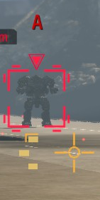
Let’s continue by exploring what the model "sees" in the vicinity of the target designator, as this might give a better idea of what vocabulary we might have to use for a successful prompt. First, directly, by cropping the image to just the designator.

gotowce moondream designator base crop
Figure 5. Image being analyzed below.
designator_location_base_image = [860, 418, 955, 512]

base_image_designator_crop = sv.crop_image(base_image, xyxy=designator_location_base_image)
infer(base_image_designator_crop, "Describe the image")

The image features a robot with a dark silhouette, standing in a red-framed area. The robot appears to be in a defensive stance, possibly ready to attack.

Apart from the actually internally consistent, but still amusing expression of "defensive stance, […​] ready to attack", two observations are of note here:

  • the model does seem to actually recognize mechs as "robots", which is impressive in and of itself;

  • crucially for us, it also notices a "red-frame area", i.e., our designator.

We’ll eventually return to the former, proceeding now with the latter. We know that the model is able to associate the relevant UI element with text embedding in its encoding space that results in the "red-frame". We should now determine how sensitive the model is to this "stimulus" when given a broader context. To do that in a low-tech fashion, we’ll repeatedly run the inference on an image consisting of the designator, plus a variable bit of margin. The variability will span from a relatively small dilation factor of several pixels, up to most of the image in question.

The code to perform the task is pretty simple:

def random_crop(image, base_bb, offsets_range_max: int):
    # convert to np.array to allow for vectorized operations
    bb_xyxy = np.array(base_bb)

    # define the "directions" in which the offsets are applied
    # first corner should go only "up" and "left",
    # second corner should go only "down" and "right"
    offset_direction = [-1, -1, 1, 1]

    # generate the random offsets for all BB coordinates
    offsets = np.random.randint(0, offsets_range_max, size=len(base_bb))

    # perform the "widening" calculation on the original BB
    crop_box = bb_xyxy + offset_direction * offsets

    # ensure the resultant crop BB is within the image's bounds
    repeat_max_by = len(crop_box) // len(image.size)
    clipped_crop_box = np.clip(crop_box, 0, list(image.size) * repeat_max_by)

    return sv.crop_image(image, clipped_crop_box)

Here’s an example of invocation and result:

random_crop(base_image, designator_location_base_image, 100)
gotowce moondream designator random crop

Using the function we just defined, we can now generate the descriptions in the manner we discussed with the following code:

import pandas as pd
from tqdm import tqdm


def extract_descriptions(
    source_image,
    designator_xyxy,
    min_offset=1,
    max_offset=1000,
    interval=10,
    num_iter=10,
):
    description_data = []
    for offset in tqdm(range(min_offset, max_offset, interval)):
        for iter in range(num_iter):
            cropped_image = random_crop(source_image, designator_xyxy, offset)
            desc = infer(cropped_image, "Describe the image.")
            description_data.append(
                {"max_offset": offset, "size": cropped_image.size, "description": desc}
            )

    return pd.DataFrame(description_data)

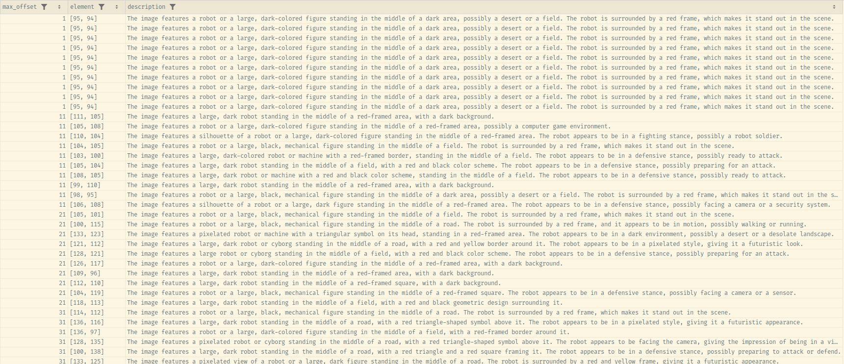
description_df =  extract_descriptions(base_image, designator_location_base_image)

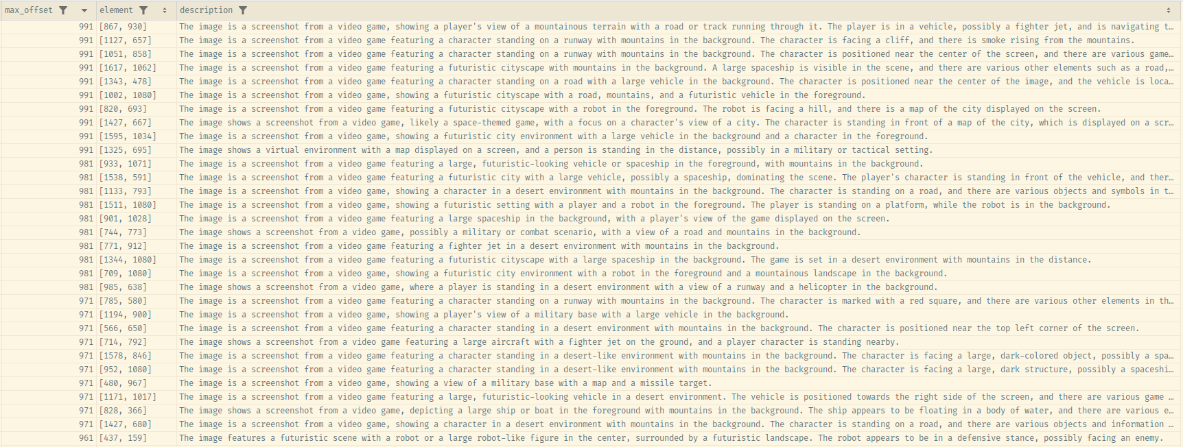
Here is the CSV file of the results obtained after an example run.

gotowce moondream designator random crop result base bottom
Figure 6. Smallest…​
gotowce moondream designator random crop result base top
Figure 7.  …​and largest maximum offsets.

Looking over the data, it is clear that the model recognizes the designator as some element, only for its importance to fall of the description inclusion threshold it in the context of the larger picture.

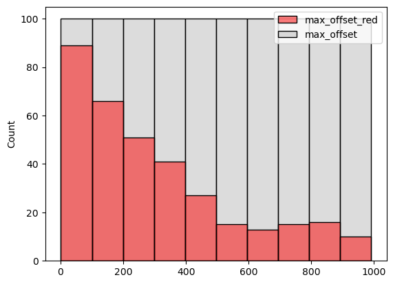
Regardless, it seems that the model recognizes the frame as a "red" something, as evidenced by this diagram:

import seaborn as sns

_SEARCH_FOR = "red"

# filter the rows that contain the search term
max_offset_with_red = description_df[
    description_df["description"].str.contains(_SEARCH_FOR)
]["max_offset"].rename(f"max_offset_{_SEARCH_FOR}")

# plot against all max offsets
sns.histplot(
    [max_offset_with_red, description_df["max_offset"]],
    palette=["red", "#bbbbbb"],
    bins=10,
)
gotowce moondream designator random crop result base hist red
Figure 8. Histogram showing a distribution of the max_offset values where the word "red" is contained in the result. Note how the frequency of the word’s presence decreases with max_offset 's value – in other words, with the size of the visible area around the designator.

Let’s run some aggregation now, so that we may see some trends in the output. We’ll proceed with that by processing the descriptions into a quasi-canonical form, and find the word "red" in the description, along with two neighboring words on each side, and then group the results. For the NLP processing, we’ll use spacy, the documentation of which contains a very nice usage primer, also explaining some basic NLP concepts.

from functools import partial
from typing import Optional
import spacy

_RED_VICINITY = 2
_SEARCH_FOR = "red"
_FIELD_DESCRIPTION = "description"

nlp = spacy.load("en_core_web_sm")


def word_neighborhood(
    source: str, lemmatized_word: str, neighborhood_size: int
) -> Optional[str]:
    """Takes a single description, runs basic NLP to obtain lemmatized sentences, and extracts
    `neighborhood_size` words around the `lemmatized_word`, including the latter."""

    # run the basic NLP pipeline
    doc = nlp(source)

    try:
        # we assume there's only one sentence that has the word
        # not a fan of exception-driven logic, but it's cleaner in this case
        word_sentence = [
            s for s in doc.sents if any(t.lemma_ == lemmatized_word for t in s)
        ][0]
    except IndexError:
        return None

    # get the lemmatized version of the sentence, without
    # stopwords and punctuation
    processed_sentence = [
        t.lemma_ for t in word_sentence if not t.is_stop and t.is_alpha
    ]

    word_pos = processed_sentence.index(lemmatized_word)

    # an alternative would be to use the various Matcher facilities in spaCy,
    # but the chosen approach is a bit less cumbersome, doesn't require as much
    # knowledge of spacy to read, and we don't care for efficiency in this case
    return " ".join(
        processed_sentence[
            max(0, word_pos - neighborhood_size) : word_pos + neighborhood_size + 1
        ]
    )


def process_description(description_df: pd.DataFrame) -> pd.DataFrame:
    # apply the word neighborhood function to the description column
    with_red_vicinity = description_df.copy()
    with_red_vicinity[_FIELD_DESCRIPTION] = with_red_vicinity[_FIELD_DESCRIPTION].apply(
        partial(
            word_neighborhood,
            lemmatized_word=_SEARCH_FOR,
            neighborhood_size=_RED_VICINITY,
        )
    )

    # group by description and aggregate the other fields
    return (
        with_red_vicinity.groupby(_FIELD_DESCRIPTION)
        .agg(
            {
                "max_offset": np.median,
                "size": list,
                # Add other fields as needed
            }
        )
        .reset_index()
    )


with_red_vicinity_unique = process_description(description_df)

with_red_vicinity_unique
gotowce moondream designator random crop result base processed bottom
Figure 9. Top 20 grouped smallest offsets…​
gotowce moondream designator random crop result base processed top
Figure 10.  …​and top 20 largest ones.

Unfortunately, we confirm the trend we were seeing in the "raw" data – the designator becomes less "distinct" in larger inputs.

In other words, we can try to use the "small detail" text for our BB prompt, but we will not get expected results:

bbox_to_annotation(base_image, "Bounding box of the red square frame border.")
gotowce moondream designator base crop with target bottom crop
Figure 11. The BB is at the very bottom-left, not where we expect it to be.

"Prompt engineering" of input images

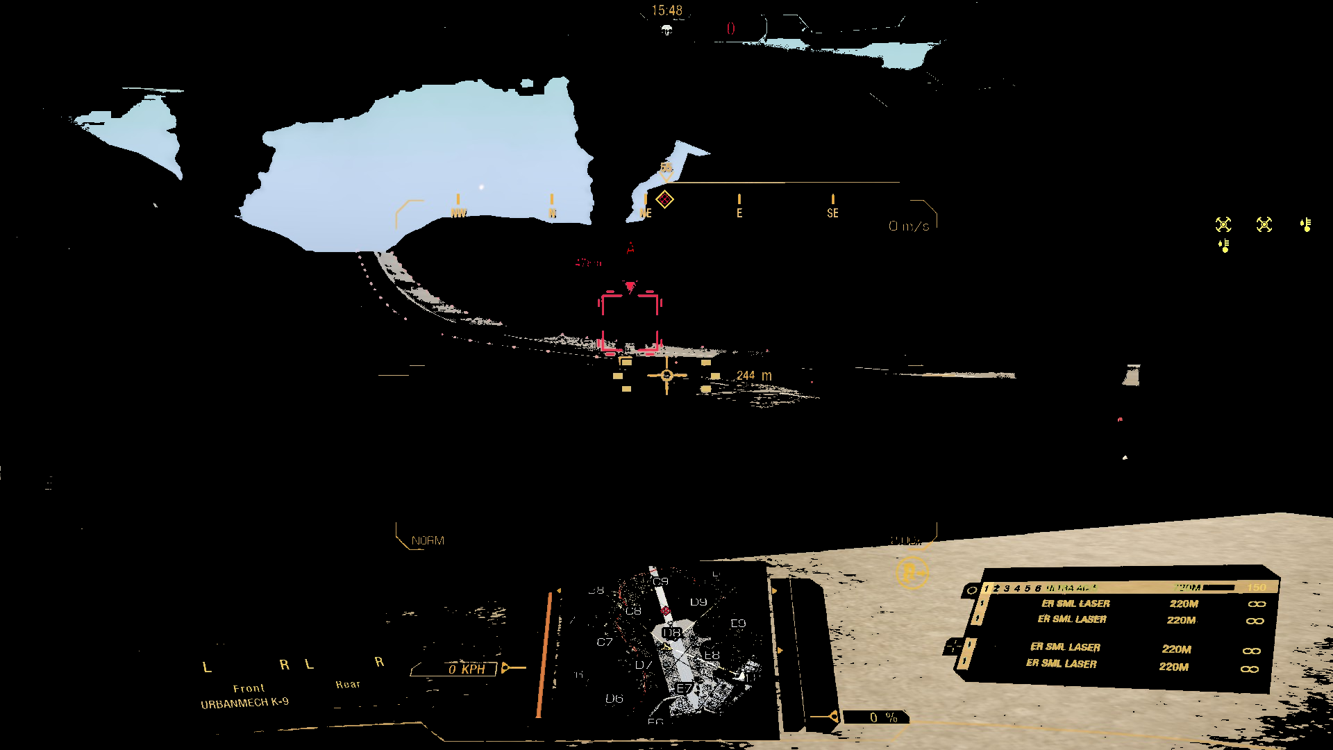
An alternative way for us to make it easier for the model to "focus" on what we want is to limit the information available in the scene. To do that, we’ll use the insights from the previous entry to simply color-threshold the input image.

Specifically, we’ll mask everything below the 90th percentile of the color threshold for the designators we’ve analyzed, which is color value 177 for the red channel. One way to do this would be to use OpenCV[8]. Here are the relevant code snippets and inference results:

import cv2 as cv

def mask_red_channel_opencv(image, threshold=177):

    # using the inRange function, which is slightly more readable than
    # creating a mask just based on numpy operations, i.e., something like this:
    # mask = (image[:, :, 2] >= threshold).astype(np.uint8) * 255

    mask = cv.inRange(image, (0, 0, threshold), (255,) * image.shape[-1])

    return image & np.expand_dims(mask, axis=-1)
gotowce moondream designator base crop with target color thresh
Figure 12. Color thresholded image.
infer(masked_image, "Describe the image.")

The image is a screenshot from a video game featuring a dark background with various elements and graphics. It appears to be a screenshot from a space shooter game, possibly from the "URBANMECHE K-9" series.

bbox_to_annotation(
    masked_image,
    "Bounding box of the small red frame area.",
)
gotowce moondream designator base crop with target color thresh des box
Figure 13. Designator-detection attempt after color thresholding.

That’s more like it, but still, not perfect. Moreover, the base image is pretty much the "ideal" screenshot. For a more busy scene…​

masked_image_busy = sv.cv2_to_pillow(
        mask_red_channel_opencv(sv.pillow_to_cv2(busy_image))
    )
gotowce moondream designator busy crop with target color thresh
Figure 14. Color thresholded image - "busy" scene.
infer(masked_image_busy, "Describe the image.")

The image is a screenshot from a video game featuring a space theme, with various elements of a spaceship cockpit and a cityscape in the background.

bbox_to_annotation(
    masked_image_busy,
    "Bounding box of the small red frame area.",
)
gotowce moondream designator busy crop with target color thresh des box
Figure 15. In case you can’t see the location of the bounding box – it’s almost the entirety of the image.

No dice here, either.

Conclusions for Moondream

Like with YOLO-World, it looks like there’s simply a mismatch between what the model was trained to detect, and what we want from it. Perhaps there is a specific prompt that does let the model identify the target designator flawlessly. I’m sure that if there is, I will be made aware of it in 5 minutes of posting this blog entry. However, that prompt certainly can’t be described as easily discoverable.

Again, similarly to YOLO-World, Moondream can certainly be fine-tuned to output what we want, but that is out of scope for this entry, as defined in the introduction.

It would be remiss to leave our consideration of Moondream, and similar distilled LVMs, at this. One thing must be stressed – the models are considerably more powerful than what we’ve shown so far.

Case in point:

bbox_to_annotation(
    busy_image,
    "Bounding box of the mech on the left.",
)

bbox_to_annotation(
    busy_image,
    "Bounding box of the mech on the right.",
)
gotowce moondream designator base mech left
gotowce moondream designator base mech right

The two prompt results show:

  1. Not only does the model readily recognize "robot-like" shapes;

  2. it also has an embedding mapping rich enough that it can directly map the phrase "mech" onto these shapes;

  3. the detected area actually does roughly correspond to the mechs in the scene.

All this is to say: Moondream, and models like it, are certainly powerful enough to potentially serve our main purpose, i.e., detecting the mechs on the screen, with only some tweaking. We’ll revisit this opportunity space in future entries.

Do we even need the designator? Looking into auto-segmentation via SAM 2

Throughout the current body of the blog series, we’ve operated on an assumption that extracting the designator images is our best bet of building a training set for the "final" mech detection model. Is that necessarily the case?

Those knowing a certain "law" already know the answer. Indeed, one of the changes in recent years has been the appearance of modern generalized image segmentation models[9]. The output thereof can be then used as training data for the target detection models.

We’ll try out a relatively recent one, Segment Anything 2 from Meta (née Facebook), available alternatively on Hugging Face. There’s also a rather impressive landing page, with various demos, including interactive ones.

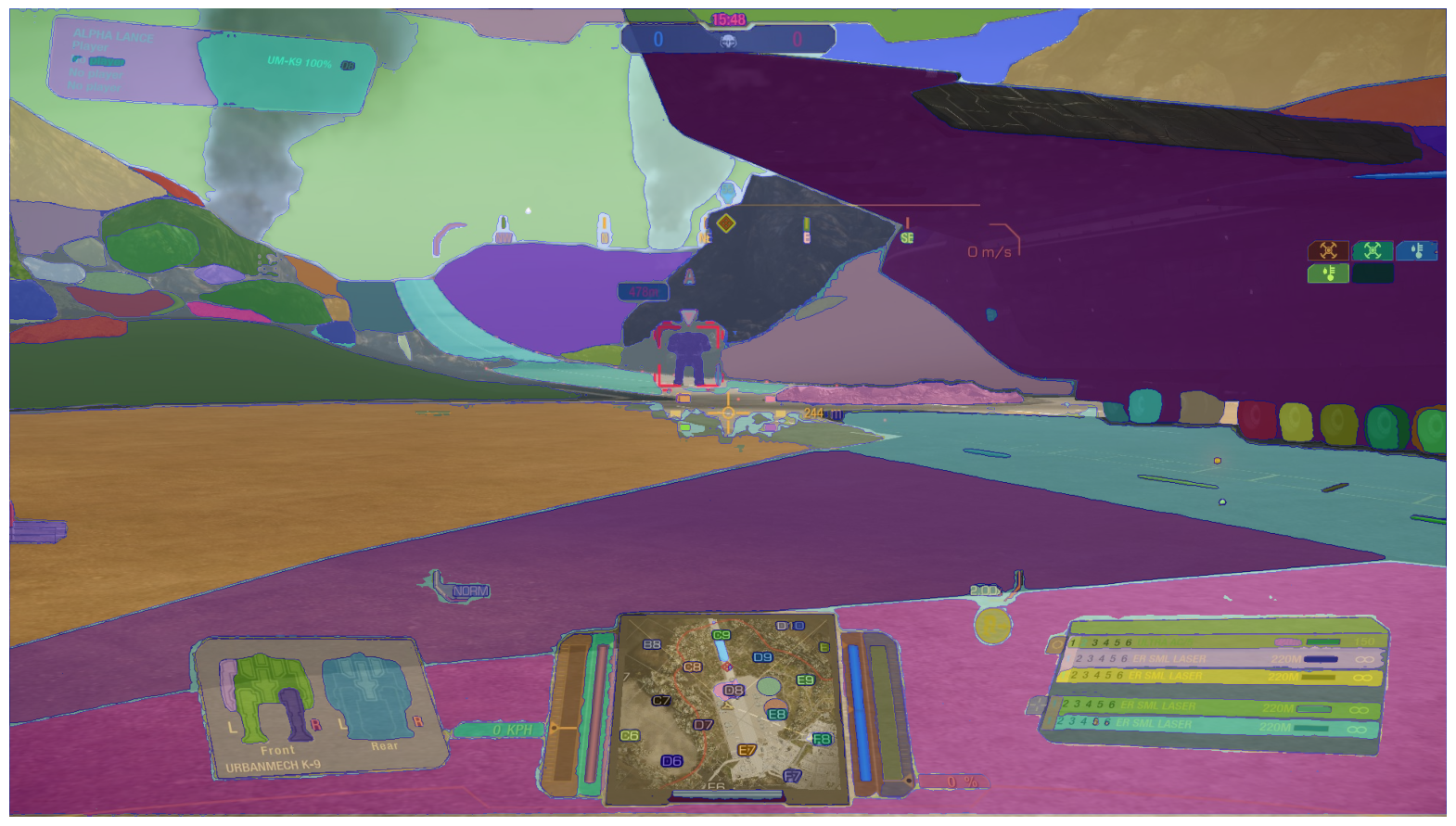
Perusing the docs, notebooks, etc., we should notice quite quickly what the major trait is of the model, setting it apart from the "classical" segmentation models. Namely, it can provide complete, or near-complete segmentation of an image without any other input, as evidenced by the screenshot below…​

gotowce sam2 unprompted base image
gotowce segmentation example
Figure 16. Our base image, auto-masked by SAM 2. Generated by following example code from this notebook, specifically the "Automatic mask generation options" section.
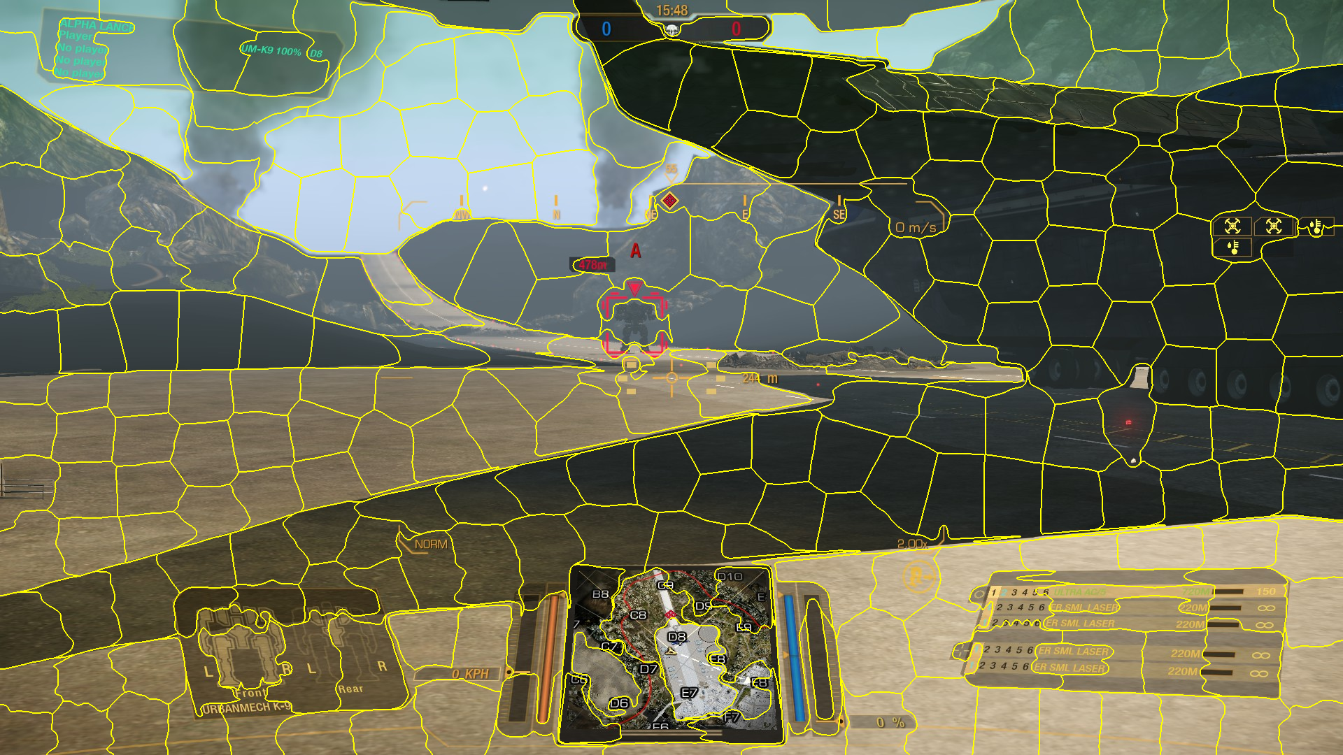
For comparison: the same image, segmented using SLIC, a technique introduced in 2012. Note that the segmentation provides our desired result as well in this case; in other words, the ability of SAM 2 to just fully segment the image to our spec is not the thing we’re looking for.

Its real power lies in the ability to segment images based on a point prompt. Well, that and being able to process videos based on that original prompt (and being resilient against occlusions, and other things…​).

Let’s see a little demonstration. The code here is heavily derived from Roboflow’s blog entry, authored by Piotr Skalski, on SAM 2, the primary adaptation being generalizing most of the logic into a single-function API[10]:

# again, this is mostly code from
# https://blog.roboflow.com/sam-2-video-segmentation/
# reorganized and slightly amended

import cv2 as cv
import numpy as np
import pandas as pd
import supervision as sv

from pathlib import Path

def get_masks_as_detections(object_ids, mask_logits) -> sv.Detections:
    """Converts SAM 2 output to Supervision Detections."""
    masks = (mask_logits > 0.0).cpu().numpy()
    N, X, H, W = masks.shape
    masks = masks.reshape(N * X, H, W)

    return sv.Detections(
        xyxy=sv.mask_to_xyxy(masks=masks), mask=masks, tracker_id=np.array(object_ids)
    )


def add_points_to_predictor(predictor, inference_state, point_data: pd.DataFrame):
    """Add points to SAM 2's inference state.

    This function assumes it receives a DF with the columns:
    ["point_xy", "object_id", "label", "frame_id"]

    where "label" is 1 or 0 for a pos/neg example.
    """

    # aggregate by frame and object, to conform to batching modus
    # of predictor.add_new_points
    aggregated = point_data.groupby(["frame_id", "object_id"]).agg(list)

    for (frame_id, object_id), row in aggregated.iterrows():

        points = np.array(row["point_xy"], dtype=np.float32)
        labels = np.array(row["label"])

        predictor.add_new_points(
            inference_state=inference_state,
            frame_idx=frame_id,
            obj_id=object_id,
            points=points,
            labels=labels,
        )

def ensure_frames_generated(source_video: Path, frame_dir_root: Path) -> Path:
    """Checks if the frame images, necessary for SAM 2's state init and processing, are present.

    If not, generates and saves them to the corresponding `frame_dir_root` subdirectory.
    """

    video_name = source_video.stem

    frame_dir = frame_dir_root / video_name

    # a simple check - if the video for the directory exists,
    # we assume the frames are already generated
    if not frame_dir.exists():
        sink = sv.ImageSink(target_dir_path=frame_dir, image_name_pattern="{:04d}.jpeg")

        with sink:
            for frame in sv.get_video_frames_generator(str(source_video)):
                sink.save_image(frame)

    return frame_dir


def segment_video(
    predictor,
    source_video: Path,
    point_data: pd.DataFrame,
    target_video: Path,
    label_annotator: sv.LabelAnnotator,
    mask_annotator: sv.MaskAnnotator,
    frame_dir_root: Path = Path("./video_frames"),
):
    frame_dir = ensure_frames_generated(source_video, frame_dir_root)

    # init model's state on the video's frames
    inference_state = predictor.init_state(video_path=str(frame_dir))

    # add segment guidance points to the model
    add_points_to_predictor(predictor, inference_state, point_data)

    video_info = sv.VideoInfo.from_video_path(str(source_video))

    frames_paths = sorted(
        sv.list_files_with_extensions(directory=frame_dir, extensions=["jpeg"])
    )

    with sv.VideoSink(str(target_video), video_info=video_info) as sink:
        for frame_i, object_ids, mask_logits in predictor.propagate_in_video(
            inference_state
        ):
            frame = cv.imread(str(frames_paths[frame_i]))

            detections = get_masks_as_detections(object_ids, mask_logits)

            frame_annotated = label_annotator.annotate(frame, detections)
            frame_annotated = mask_annotator.annotate(frame_annotated, detections)
            sink.write_frame(frame_annotated)

which can be invoked like this:

segment_video(
    predictor,
    source_video=Path(SOURCE_VIDEO),
    point_data=point_data,
    target_video=Path(TARGET_VIDEO_PATH),
    label_annotator=sv.LabelAnnotator(
        color=sv.ColorPalette.DEFAULT,
        color_lookup=sv.ColorLookup.TRACK,
        text_color=sv.Color.BLACK,
        text_scale=0.5,
        text_padding=1,
        text_position=sv.Position.CENTER_OF_MASS,
    ),
    mask_annotator=sv.MaskAnnotator(
        color=sv.ColorPalette.DEFAULT, color_lookup=sv.ColorLookup.TRACK
    ),
)

The predictor value is the result of a sam2.build_sam.build_sam2_video_predictor call, the instructions for setting up which are available in the relevant documentation. In all examples here, we are using the "large" model variant.

Since we’re switching from images to video, we need to actually choose a video snippet. We’ll go with this one:

As you can see, the video can potentially be challenging to segment – the color palette is muted and homogenous, the objects of interest are either small, occluded, or blend with the background well. Nevertheless, let’s try marking a single point – specifically on the very fist visible mech up in front – and see how SAM 2 performs:

That’s actually impressive. The model does manage to keep up with both the objects and the camera’s movement, only "picking up" some extraneous elements, but never extending the mask to an unacceptable level. The only bigger hangup is it losing the object and switching tracking to another one after the zoom level switch – again, nothing concerning, as there’s no indication SAM 2 should be resilient against that.

OK, so we’ve covered a single object, but, in this snippet, a grand total of 5[11] are available to segment. We extend the point data to the following form:

import pandas as pd

# as a reminder, "label" denotes whether
# the example is "positive" or "negative"
#
# we identify our "segmentation tracks"
# by the "object_id" field

point_data = pd.DataFrame(
    [
        [[1122, 347], 1, 1, 52],
        [[1167, 348], 2, 1, 52],
        [[1030, 350], 1, 1, 76],
        [[880, 338], 2, 1, 113],
        [[900, 355], 2, 0, 113],
        [[1675, 435], 3, 1, 130],
        [[1508, 446], 4, 1, 131],
        [[1553, 444], 4, 0, 131],
        [[1867, 427], 5, 1, 145],
        [[1202, 391], 4, 1, 363],
        [[1258, 435], 3, 1, 363],
        [[755, 324], 2, 1, 393],
        [[1145, 399], 4, 1, 436],
        [[1155, 331], 4, 1, 436],
        [[1062, 383], 4, 1, 615],
        [[1011, 391], 3, 1, 636],
    ],
    columns=["point_xy", "object_id", "label", "frame_id"],
)

For reference and visualization, here is the representation of the example points on the respective frames, as well as the initial segmentation provided by SAM 2’s model state.

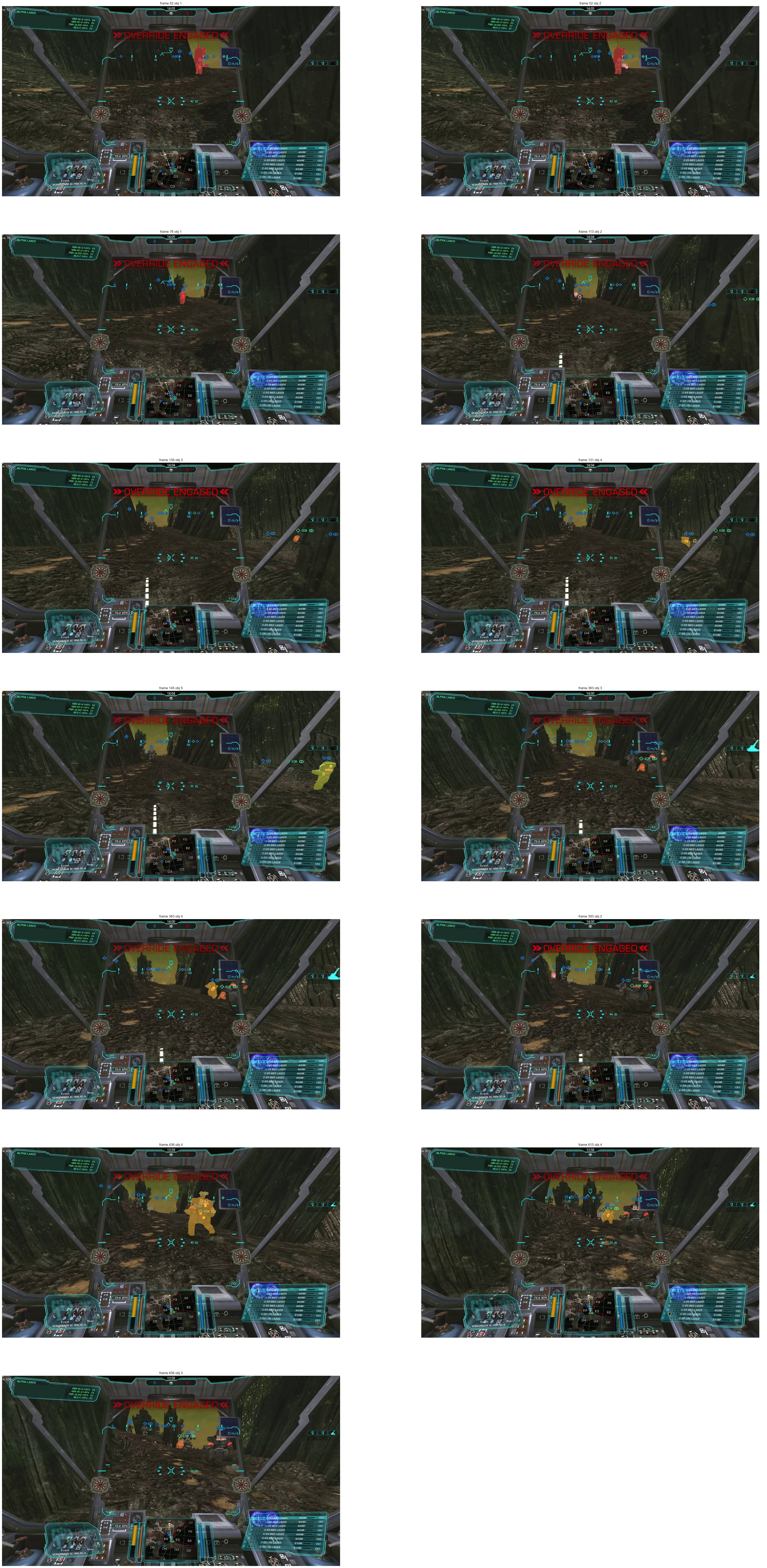
gotowce sam2 frame debug grid
Figure 17. The debug frames. Note the subtitles. Example points are denoted as circles – filled for "positive", hollow for "negative". Masks generated from the model’s inference state while adding the points are also provided. Click here for a larger version.

We can see that the static image masking does look promising. The biggest problem is that SAM 2 is a bit "greedy", and often incorporates parts of the background – see especially the first frame presented – hence the need for several negative examples. We also had to provide additional example points for objects that "started out" adjacent, or even overlapping. Again, still a good show so far, given the difficulty of the input video.

From the examples provided, we get the following segmentation results:

Comparing to the single-point example, the most notable phenomenon is a markedly reduced tracking ability of the "original" object (denoted as 0). This is likely due to attempting simultaneous segmentation on another mech (denoted as 1) that’s passing right behind 0. Overall, the model is unable to persistently track virtually any of the objects without further point examples, and even then, it eventually loses persistence. Interestingly, it does manage persist the tracking of one object over the zoom sequence (4), which means SAM 2’s anti-occlusion facilities are quite powerful.

Nevertheless, we must remind ourselves that we are not investigating SAM 2 for tracking capabilities, but to provide a source of training data for detection. And, for this purpose, it seems like a promising direction. The model produces masks that are almost always more precise than the equivalent of the target designator’s shape (something we haven’t talked about yet – even when we do get the designators, a cleanup step will still be necessary before we proceed with actual training, or fine-tuning, of a detection model).

Additionally, we’ve imposed quite a challenge on SAM 2. There’s plenty of "real world" use cases where the model would be likely to perform with much greater fidelity, and so provide even better annotation data.

The only gripe is resource consumption – even the "tiny" version of SAM 2 uses too much VRAM for most consumer GPUs. The hope lies in the larger community creating derivatives that require less memory, while having similar performance.

"Mainstream" LLMs

While things were a bit different even a year ago (due to lacking image-assisted prompt possibilities), it would now be remiss to not include a comparison of processing through the "mainstream" LLMs. We’re going to take a look at two families of them: Anthropic’s Claude and OpenAI’s GPT-4o.

The plan is as follows – first, we’re going to supply the demo image with the following prompt:

The image is a screenshot of a video game. On the screenshot, there is a target designator, shaped like a square with middle portions of its sides missing, all colored red. Provide the bounding box pixel coordinates of this designator.

We’re going to repeat the same text prompt with the "busy" image. Finally, we’re going to use one of the frame images from the test video, i.e., this one:

gotowce reference frame 145
Figure 18. The reference frame we will be using, or "the third image".

and the prompt:

The image is a screenshot from a video game in the BattleTech/MechWarrior franchise. Provide bounding box locations of all the mechs in the image.

We’ll adapt this preliminary plan in case a potential for additional insights manifests itself.

Claude

Spoiler: this won’t go well. Starting with demo image and the specified prompt:

I apologize, but I’m not able to provide exact pixel coordinates from the image. However, I can describe the location and appearance of the red target designator you’re referring to:

The red target designator is located roughly in the center of the image, slightly below the midpoint vertically. It’s surrounding what appears to be a mech or large robotic figure standing on a road or runway.

The designator consists of a square shape with the middle portions of each side missing, creating a crosshair-like effect. Inside this designator is a distance readout showing "478m".

If you need precise pixel coordinates, you would need to use an image editing tool or specialized software to analyze the image. I can only provide descriptive information based on what I see in the image.

(emphasis added)

So, unfortunately, it looks like Claude immediately turns out to be a dud for our purposes. Now, it’s not all bad – it does recognize both the designator and the mech in the image. We note also that Claude considers the distance readout as being inside the designator; we’ll get back to this observation in the ChatGPT section.

Just not to end Claude’s exploration too abruptly, let’s see what it has to say for some other images and prompts. Here’s what it outputs when provided the "busy" image, with an adapted prompt:

gotowce claude busy image

Unfortunately, Claude doesn’t seem to recognize the mech that’s actually being targeted – there was a bit of hope the designator itself would provide sufficient context. At least it does identify the two other relevant objects in view. However, it describes the one on the left erroneously as hostile – quite obviously, due to the "friendly" marker above visually separated from the mech by one of the UI elements.
Interestingly, Claude does appear to have some information about the franchise, as it correctly references the existence of the assault weight class[12]. Not surprising, 'though – BattleTech is enjoying its 40-year anniversary right about now.

Finally, let’s see if Claude can at least recognize mechs in a more challenging screenshot:

gotowce claude result frame 145

Disappointing as well: the correct answer is 5, not counting the player.

Before we conclude, we must note that the prompts were answered by the free version of Sonnet. While this may seem unfair, Claude all but disqualified itself by refusing to provide bounding box coordinates, apparently by design. Frankly, the author is unwilling to splurge >20€ just to check if the Pro version has a different system pre-prompt.

Otherwise, it’s worth pointing out that Claude, for our use cases, appears to have similar capabilities to a model such as Moondream.

ChatGPT

We’re using GPT-4o, as o1-preview doesn’t seem able to ingest images currently. For the demo image, using the prompt specified in the section intro, the model does provide a bounding box: (810, 370, 960, 520). The coordinates translate to the following clip:

gotowce chatgpt base image

Partially true, but not exact. The model seems to consider the distance readout as part of the designator. This quirk is not only present here but also in Claude and in Moondream. Honestly, not entirely sure what is the reason. The best guess is these sorts of UI elements, (i.e., designators) indeed often have supplementary icons or text "attached" to them, and this is reflected in whatever common data sets were used to train the models. So, for the model, the designator indeed comprises both the element itself and any "add-ons", an effect similar to the well-known "huskies are on snowy background" class of error – if it even can be considered an "error".

A follow-up prompt:

The bounding box provided is too large. It should only contain the designator’s square shape itself. Please refine the coordinates.

yields (842, 406, 927, 491):

gotowce chatgpt base image refined

better, but still not ideal.

Let’s move on to the busy image, where the bounding box is given as (617, 32, 1775, 1055):

gotowce chatgpt busy image
Figure 19. Yes, this is the "bounding box" provided by ChatGPT for the "busy" image.

which, as we already guess from the coordinates alone, is way too imprecise – although, in fairness, it does include the designator itself. Funnily enough, the model, when requesting refinement, eventually "gives itself up" with this choice snippet:

It appears that my current attempt still did not yield the correct bounding box for the smaller red designator. Given the complexity of identifying the exact designator in this image, I would recommend a more manual analysis or specialized visual inspection using specific graphic tools. If you prefer, you could manually examine pixel clusters using an image editor to isolate the exact region you’re interested in.

All right, let’s do some follow-ups with "smarter" queries, like we did with Claude.

gotowce chatgpt busy image mech bbs
Figure 20. Result of the BB query on the "busy" image.

For the "BB location" prompt (the second one from the intro), ChatGPT seems to provide similar results as Moondream. Note that the image above was generated "manually", which is actually not strictly necessary – 4o absolutely can, and will, when asked for, draw the bounding boxes automatically.

gotowce chatgpt busy image count
Figure 21. Result of an object-counting query on the "busy" image.
gotowce chatgpt frame 145 count
Figure 22. Result of a similar query on the reference video frame.

ChatGPT returns similar results as Claude. When pressed with the suggestion of the correct answer (5), and asked to provide bounding boxes, it does so, but hallucinates heavily, and returns completely incorrect BBs[13].

gotowce chatgpt frame 145 bbs
Figure 23. Yeah, no.

Summary

We have undergone quite a journey in this post. What then, are its takeaways?

The primary one, perhaps: for specialized use cases, such as, apparently, ours, there is still no free lunch. Most popular vision models are trained principally on "real world" images, with "real world" objects. No wonder – most of the use cases need those. For others, however, non-trivial work needs to be done, at least in the form of fine-tuning. Bummer on the one hand, yet on the other, a confirmation that a lot of interesting problem-solving is still there to explore.

The second takeaway flows from the first: even the models of the "large" corps, trained while burning through the equivalent electricity consumption of a small country (not an exaggeration), are unable to give answers to our problems for "free" – not because they are not deficient or borderline sci-fi at times, but they simply weren’t trained for this. And speaking of "free", were they even capable of performing the required tasks flawlessly, they’d still be prohibitively expensive for such a hobby use case – we’re talking dollars on the thousands of images/frames.
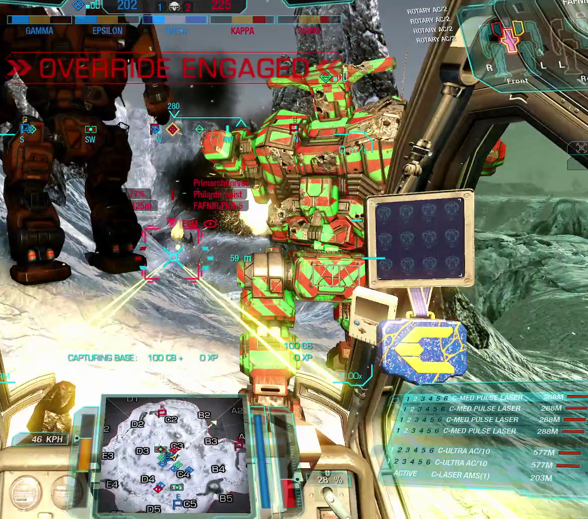
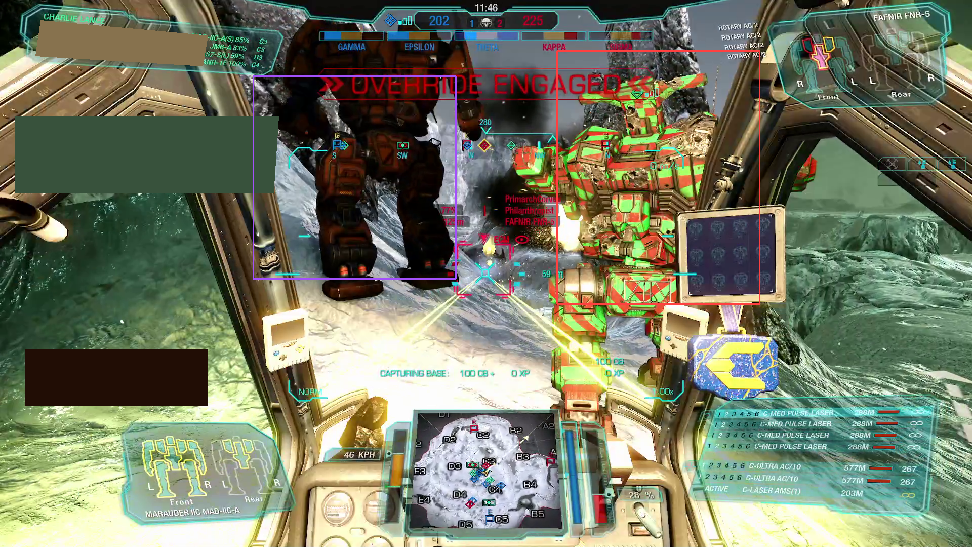
Finally, and most importantly, some conclusions relevant to the "offline" models we’ve gone through:

  • YOLO-World seemed to be the weakest for our use case, but even it can probably be made to work well with some fine-tuning, and not only for finding designators, but for mechs themselves. The latter, of course, presents a chicken-and-egg problem, as we need the data somehow.

  • Distilled VLMs such as Moondream work even better, and, perhaps in the near future, will be good enough to employ for the use case of detecting video-game-specific objects without any fine-tuning. We must, however, be mindful of their complexity and resource requirements, barely runnable on the majority of consumer-grade hardware. We cannot then unequivocally settle on them just yet.

  • Modern generalist segmentation models such as SAM 2 offer the most intriguing opportunity – sure, they’re not as convenient as auto-detecting target designators, but:

    • they potentially output more precise annotation information via the masks;

    • with a couple of days of work, the input data yield can surpass the autodetection approach, as we can locate and annotate arbitrary objects on the screen, not just the ones surrounded by a specific UI element;

    • however, we will need to wait for less power-hungry derivatives for this to work in an acceptable timeframe.

Overall, we’re still not quite in the singularity that’s being heralded as coming soon for some time now, not even for "simple" tasks such as computer vision. But that’s good! It means there’s still a lot of interesting work to be done, and a lot of interesting problems to solve.

In the next entries, we will proceed with that problem-solving. We’ll be using several approaches to precisely extract the target designators, and we will start doing what we should have been doing already – comparing the performance and resource usage of various approaches in a diligent manner. We probably will even revisit some of the models (or their derivatives) discussed here. For now – until next time!


1. …​except for getting the models to play nice with drivers, interfacing libs such as CUDA, and so on. War, war never changes…​
2. See section 4.2 "Pre-Training" of the paper for the full collection of datasets.
3. There’s also the def column that can be wrangled with some basic NLP, but that is unlikely to bring any novel or contradicting conclusions.
4. It also manages that if you just provide "dropship" as a class, funnily enough.
5. And no, it also won’t detect a "mech" or "robot", at least in this screenshot.
6. Without paying for hardware worth as much as a good new car, that is.
7. From March this year, so already somewhat out of date, of course.
8. We could, of course, just use Pillow, as that’s what we’re starting with, but OpenCV’s API is slightly less cumbersome for the particular use case.
9. Not that generalized segmentation models or algorithms didn’t exist before – quite the opposite, of course. It’s just that the current crop is considerably more effective.
10. Ideally, for actual usage, the code should have been generalized to something like a Builder-pattern object. That would render the code a bit less digestible for the purpose of a blog-contained example, however.
11. Not counting the Rifleman II mech visible at the very end, crossing a gorge.
12. And the mech in question is an assault-class mech to boot.
13. For completeness, the prompt was: "The answer is actually 5 (five), not counting the player’s mech. Can you provide bounding box locations of these five mechs?"